AUDIO AND VISUAL SYSTEM (for Radio and Display Type), Diagnostic DTC:B15C3

| DTC Code | DTC Name |
|---|---|
| B15C3 | Speaker Output Short |
DESCRIPTION
This DTC is stored when a malfunction occurs in the speakers.
| DTC Code | DTC Detection Condition | Trouble Area |
|---|---|---|
| B15C3 | A short is detected in the speaker output circuit. |
|
WIRING DIAGRAM
INSPECTION PROCEDURE
PROCEDURE
-
CHECK HARNESS AND CONNECTOR
-
*1: for RH Side
-
*2: for LH Side
-
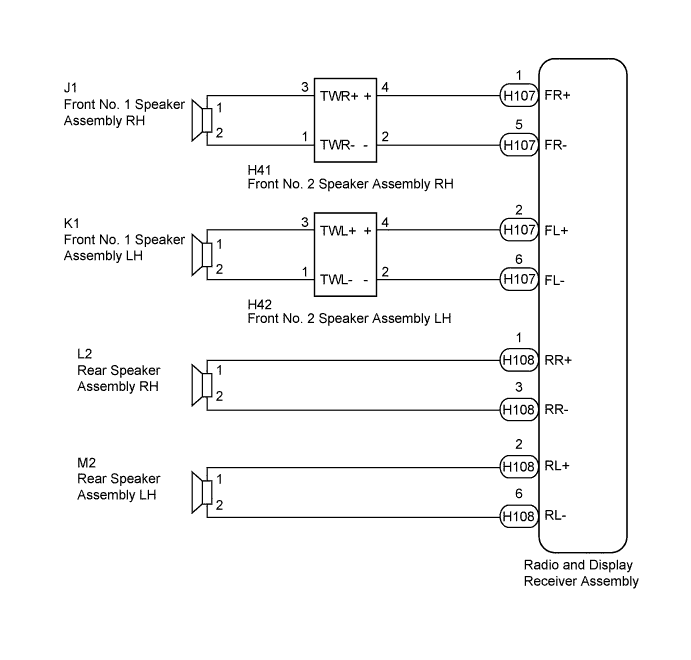
Disconnect the H107 and H108 radio and display receiver assembly connectors.
-
Disconnect the J1*1 and K1*2 front No. 1 speaker assembly connectors.
-
Disconnect the H41*1 and H42*2 front No. 2 speaker assembly connectors.
-
Disconnect the L2*1 and M2*2 rear speaker assembly connectors.
-
Measure the resistance between each of the radio and display receiver assembly and the front No. 2 speaker assembly to check for an open circuit in the wire harness.
Standard Resistance Tester Connection Condition Specified Condition H107-1 (FR+) - H41-4 (+) Always Below 1 Ω H107-5 (FR-) - H41-2 (-) H107-2 (FL+) - H42-4 (+) H107-6 (FL-) - H42-2 (-) -
Measure the resistance between each of the front No. 2 speaker assembly and front No. 1 speaker assembly to check for an open circuit in the wire harness.
Standard Resistance Tester Connection Condition Specified Condition H41-3 (TWR+) - J1-1 Always Below 1 Ω H41-1 (TWR-) - J1-2 H42-3 (TWL+) - K1-1 H42-1 (TWL-) - K1-2 -
Measure the resistance between each of the radio and display receiver assembly and the rear speaker assembly to check for an open circuit in the wire harness.
Standard Resistance Tester Connection Condition Specified Condition H108-1 (RR+) - L2-1 Always Below 1 Ω H108-3 (RR-) - L2-2 H108-2 (RL+) - M2-1 H108-6 (RL-) - M2-2 -
Measure the resistance between each speaker assembly and body ground to check for a short circuit in the wire harness.
Standard Resistance Tester Connection Condition Specified Condition J1-1 - Body ground Always 10 kΩ or higher J1-2 - Body ground K1-1 - Body ground K1-2 - Body ground H41-4 (+) - Body ground H41-2 (-) - Body ground H42-4 (+) - Body ground H42-2 (-) - Body ground L2-1 - Body ground L2-2 - Body ground M2-1 - Body ground M2-2 - Body ground
NG 
REPAIR OR REPLACE HARNESS OR CONNECTOR
OK 
-
-
INSPECT FRONT NO. 1 SPEAKER ASSEMBLY
-
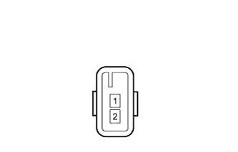
Disconnect the J1*1 and/or K1*2 front No. 1 speaker assembly connector.
-
*1: for RH Side
-
*2: for LH Side
-
-
Measure the resistance according to the value(s) in the table below.
Standard Resistance Tester Connection Condition Specified Condition 1 - 2 Always 4 Ω
NG
REPLACE FRONT NO. 1 SPEAKER ASSEMBLY Click here
OK
-
-
INSPECT REAR SPEAKER ASSEMBLY
-
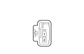
Disconnect the L2*1 and/or M2*2 rear speaker assembly connector.
-
*1: for RH Side
-
*2: for LH Side
-
-
Measure the resistance according to the value(s) in the table below.
Standard Resistance Tester Connection Condition Specified Condition 1 - 2 Always 4 Ω
NG
REPLACE REAR SPEAKER ASSEMBLY Click here
OK
-
-
REPLACE FRONT NO. 2 SPEAKER ASSEMBLY
-
Temporarily replace the front No. 2 speaker assembly with a new or normally functioning one Click here.
-
Check that the speaker sounds normally.
OK Malfunction disappears.
NG
REPLACE RADIO AND DISPLAY RECEIVER ASSEMBLY Click here
OK 
END (FRONT NO. 2 SPEAKER ASSEMBLY WAS DEFECTIVE)
-