DESCRIPTION
When the ignition switch is turned to ON, the battery voltage is applied to terminal IGSW of the ECM. The ECM "MREL" output signal causes a current to flow to the coil, closing the contacts of the MAIN relay and supplying power to terminal +B of the ECM.
INSPECTION PROCEDURE
-
Inspect the fuses of circuits related to this system before performing the following inspection procedure.
-
After replacing the ECM, the new ECM needs registration (Click here) and initialization (Click here).
PROCEDURE
- Click here
INSPECT ENGINE ROOM NO. 1 RELAY BLOCK
-
Remove the integration relay from the engine room No. 1 relay block.
-
Remove the EFI MAIN relay from the engine room No. 1 relay block.
-
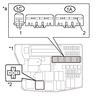
Measure the voltage according to the value(s) in the table below.
Standard Voltage Tester Connection Condition Specified Condition 1C-1 - Body ground Always 11 to 14 V 5 (EFI MAIN relay holder) - Body ground Always 11 to 14 V -
Measure the resistance according to the value(s) in the table below.
Standard Resistance Tester Connection Condition Specified Condition 1A-2 - Body ground Always Below 1 Ω 1 (EFI MAIN relay holder) - Body ground Always Below 1 Ω -
Reinstall the integration relay.
-
Reinstall the EFI MAIN relay.
Table 1. Text in Illustration *1 Engine Room No. 1 Relay Block *2 EFI MAIN Relay *a Front view of wire harness connector
(to Integration Relay)
- OKClick here
- NGClick here
-
- Click here
INSPECT INTEGRATION RELAY (IG2 RELAY)
-
Inspect the integration relay (IG2 RELAY) (Click here).
- OKClick here
- NGClick here
-
- Click here
INSPECT EFI MAIN RELAY
-
Inspect the EFI MAIN relay (Click here).
- OKClick here
- NGClick here
-
- Click here
CHECK HARNESS AND CONNECTOR (ENGINE ROOM NO. 1 RELAY BLOCK - ECM)
-
Check the wire harness between the ECM and engine room No. 1 relay block.
-
Disconnect the ECM connector.
-
Remove the integration relay from the engine room No. 1 relay block.
-
Remove the EFI MAIN relay from the engine room No. 1 relay block.
-
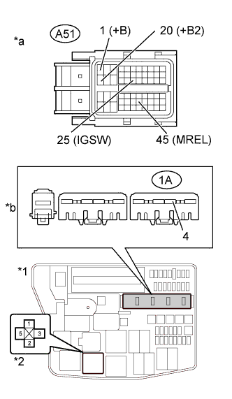
Measure the resistance according to the value(s) in the table below.
Standard Resistance Tester Connection Condition Specified Condition A51-45 (MREL) - 2 (EFI MAIN relay holder) Always Below 1 Ω A51-1 (+B) - 3 (EFI MAIN relay holder) Always Below 1 Ω A51-20 (+B2) - 3 (EFI MAIN relay holder) Always Below 1 Ω A51-25 (IGSW) - 1A-4 Always Below 1 Ω A51-45 (MREL) or 2 (EFI MAIN relay holder) - Body ground Always 10 kΩ or higher A51-1 (+B) or 3 (EFI MAIN relay holder) - Body ground Always 10 kΩ or higher A51-20 (+B2) or 3 (EFI MAIN relay holder) - Body ground Always 10 kΩ or higher A51-25 (IGSW) or 1A-4 - Body ground Always 10 kΩ or higher Table 2. Text in Illustration *1 Engine Room No. 1 Relay Block *2 EFI MAIN Relay *a Front view of wire harness connector
(to ECM)
*b Front view of wire harness connector
(to Integration Relay)
-
Reconnect the ECM connector.
-
Reinstall the integration relay.
-
Reinstall the EFI MAIN relay.
- OKClick here
- NGClick here
-
- Click here
INSPECT ECM (IGSW VOLTAGE)
-
Disconnect the ECM connectors.
-
Turn the ignition switch to ON.
-
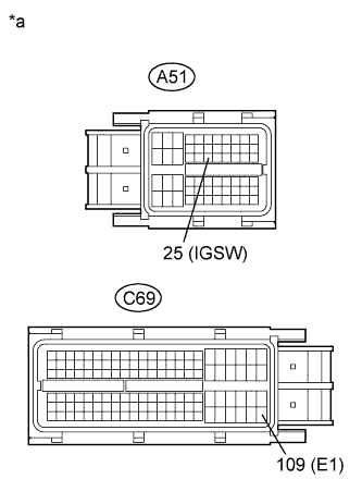
Measure the voltage according to the value(s) in the table below.
Standard Voltage Tester Connection Switch Condition Specified Condition A51-25 (IGSW) - C69-109 (E1) Ignition switch ON 11 to 14 V Table 3. Text in Illustration *a Front view of wire harness connector
(to ECM)
Table 4. Result Result Proceed to OK A NG (w/ Entry and Start System) B NG (w/o Entry and Start System) C -
Reconnect the ECM connectors.
-
-
Click here
CHECK HARNESS AND CONNECTOR (POWER MANAGEMENT CONTROL ECU - ENGINE ROOM NO. 1 RELAY BLOCK)
-
Remove the power management control ECU.
-
Remove the integration relay from the engine room No. 1 relay block.
-
Measure the resistance according to the value(s) in the table below.
Standard Resistance Tester Connection Condition Specified Condition H70-8 (IG2D) - 1A-3 Always Below 1 Ω H70-8 (IG2D) or 1A-3 - Body ground Always 10 kΩ or higher Table 5. Text in Illustration *1 Engine Room No. 1 Relay Block *a Front view of wire harness connector
(to Integration Relay)
*b Rear view of wire harness connector
(to Power Management Control ECU)
-
Reinstall the power management control ECU.
-
Reinstall the integration relay.
- OKClick here
- NGClick here
-
-
Click here
CHECK HARNESS AND CONNECTOR (IGNITION SWITCH - ENGINE ROOM NO. 1 RELAY BLOCK)
-
Disconnect the ignition switch connector.
-
Remove the integration relay from the engine room No. 1 relay block.
-
Measure the resistance according to the value(s) in the table below.
Standard Resistance Tester Connection Condition Specified Condition H6-6 (IG2) - 1A-3 Always Below 1 Ω H6-6 (IG2) or 1A-3 - Body ground Always 10 kΩ or higher Table 6. Text in Illustration *1 Engine Room No. 1 Relay Block *a Front view of wire harness connector
(to Ignition Switch)
*b Front view of wire harness connector
(to Integration Relay)
-
Reconnect the ignition switch connector.
-
Reinstall the integration relay.
- OKClick here
- NGClick here
-
- Click here
INSPECT IGNITION SWITCH ASSEMBLY
-
Disconnect the ignition switch connector.
-
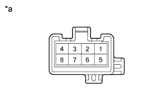
Measure the resistance of the terminals shown below.
Standard Resistance Tester Connection Switch Condition Specified Condition Between any terminals OFF 1 MΩ or higher 2 - 3 ACC Below 1 Ω 2 - 4, 6 - 7 ON Below 1 Ω 1 - 2, 2 - 4, 6 - 7, 7 - 8 START Below 1 Ω Table 7. Text in Illustration *a Component without harness connected
(Ignition Switch)
-
Reconnect the ignition switch connector.
- OKClick here
- NGClick here
-
- Click here
REPAIR OR REPLACE HARNESS OR CONNECTOR
- Click here
REPLACE INTEGRATION RELAY
- Click here
REPLACE EFI MAIN RELAY
- Click here
REPAIR OR REPLACE HARNESS OR CONNECTOR
- Click here
REPLACE ECMClick here
- Click here
REPAIR OR REPLACE HARNESS OR CONNECTOR
- Click here
CHECK ENTRY AND START SYSTEMClick here
- Click here
REPLACE IGNITION SWITCH ASSEMBLYClick here
- Click here
REPAIR OR REPLACE HARNESS OR CONNECTOR (IGNITION SWITCH - BATTERY)