ECD SYSTEM, Diagnostic DTC:P245C, P245D

| DTC Code | DTC Name |
|---|---|
| P245C | Exhaust Gas Recirculation Cooler Bypass Control Circuit Low |
| P245D | Exhaust Gas Recirculation Cooler Bypass Control Circuit High |
DESCRIPTION
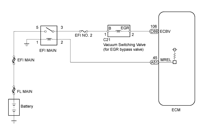
The vacuum switching valve (for EGR bypass valve) is controlled by the ECM, and the opening and closing of the EGR cooler bypass valve is performed according to the vacuum applied by the vacuum pump.
| DTC Detection Drive Pattern | DTC Detection Condition | Trouble Area |
|---|---|---|
| Ignition switch ON for 3 seconds | Open or short in the vacuum switching valve (for EGR bypass valve) for 3 seconds. (1 trip detection logic) |
|
| DTC Detection Drive Pattern | DTC Detection Condition | Trouble Area |
|---|---|---|
| Ignition switch ON for 3 seconds | Open or short in the vacuum switching valve (for EGR bypass valve) for 3 seconds. (1 trip detection logic) |
|
WIRING DIAGRAM
INSPECTION PROCEDURE
Note
-
After replacing the ECM, the new ECM needs registration Click here and initialization Click here.
-
Inspect the fuses of circuits related to this system before performing the following inspection procedure.
PROCEDURE
-
INSPECT VACUUM SWITCHING VALVE (FOR EGR BYPASS VALVE)
-
Inspect the vacuum switching valve (for EGR bypass valve) Click here.
NG 
REPLACE VACUUM SWITCHING VALVE (FOR EGR BYPASS VALVE) Click here
OK 
-
-
CHECK VACUUM SWITCHING VALVE (POWER SOURCE CIRCUIT)
-
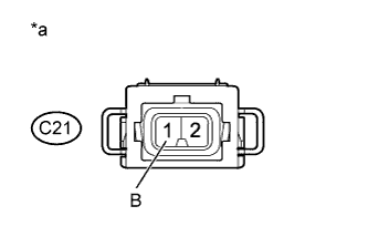
Text in Illustration *a Front view of wire harness connector
(to Vacuum Switching Valve (for EGR bypass valve))
Disconnect the vacuum switching valve (for EGR bypass valve) connector.
-
Measure the voltage according to the value(s) in the table below.
Standard Voltage Tester Connection Switch Condition Specified Condition C21-1 (B) - Body ground Ignition switch ON 11 to 14 V -
Reconnect the vacuum switching valve (for EGR bypass valve) connector.
NG
REPAIR OR REPLACE HARNESS OR CONNECTOR Click here
OK
-
-
CHECK HARNESS AND CONNECTOR (VACUUM SWITCHING VALVE (FOR EGR BYPASS VALVE) - ECM)
-
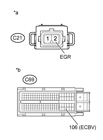
Text in Illustration *a Front view of wire harness connector
(to Vacuum Switching Valve (for EGR bypass valve))
*b Front view of wire harness connector
(to ECM)
Disconnect the vacuum switching valve (for EGR bypass valve) connector.
-
Disconnect the ECM connector.
-
Measure the resistance according to the value(s) in the table below.
Standard Resistance (Check for Open) Tester Connection Condition Specified Condition C21-2 (EGR) - C69-106 (ECBV) Always Below 1 Ω Standard Resistance (Check for Short) Tester Connection Condition Specified Condition C21-2 (EGR) or C69-106 (ECBV) - Body ground Always 10 kΩ or higher -
Reconnect the vacuum switching valve (for EGR bypass valve) connector.
-
Reconnect the ECM connector.
NG
REPAIR OR REPLACE HARNESS OR CONNECTOR Click here
OK
-
-
REPLACE ECM
-
Replace the ECM Click here.
NEXT
CONFIRM WHETHER MALFUNCTION HAS BEEN SUCCESSFULLY REPAIRED Click here
-
-
REPLACE VACUUM SWITCHING VALVE (FOR EGR BYPASS VALVE)
-
Replace the vacuum switching valve (for EGR bypass valve) Click here.
NEXT
CONFIRM WHETHER MALFUNCTION HAS BEEN SUCCESSFULLY REPAIRED Click here
-
-
REPAIR OR REPLACE HARNESS OR CONNECTOR
Tech Tips
If the voltage at the vacuum switching valve (for EGR bypass valve) connector is not 11 to 14 V, repair or replace the harness and connector between the vacuum switching valve (for EGR bypass valve) and EFI MAIN relay (including the EFI No. 2 fuse).
-
Repair or replace the harness or connector.
NEXT
-
-
CONFIRM WHETHER MALFUNCTION HAS BEEN SUCCESSFULLY REPAIRED
-
Connect the intelligent tester to the DLC3.
-
Clear the DTCs Click here.
-
Turn the ignition switch to ON for 3 seconds.
-
Enter the following menus: Powertrain / Engine and ECT / DTC.
-
Confirm that the DTC is not output again.
NEXT 
END
-