ECD SYSTEM, Diagnostic DTC:P0045

| DTC Code | DTC Name |
|---|---|
| P0045 | Turbocharger / Supercharger Boost Control Solenoid Circuit / Open |
DESCRIPTION
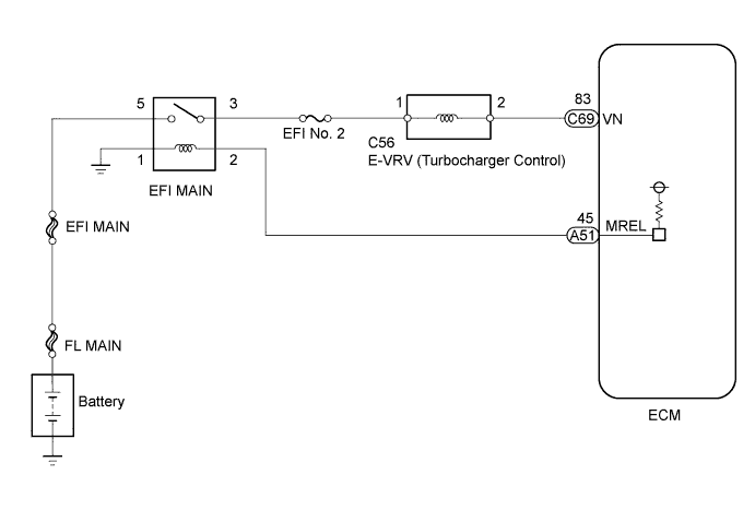
This DTC indicates that the E-VRV of the turbocharger is malfunctioning. The ECM monitors the E-VRV current to detect an open or short in the E-VRV circuit. If the current is out of the standard range, the ECM stores a DTC and illuminates the MIL immediately.
| DTC Detection Drive Pattern | DTC Detection Condition | Trouble Area |
|---|---|---|
| Ignition switch ON for 1 second | Open or short in E-VRV circuit for 0.5 seconds or more. (1 trip detection logic) |
|
Tech Tips
If DTC P0045 is stored, the following symptoms may appear.
When the nozzle vane of the turbocharger is stuck closed:
- Vehicle surge when driving with full load
When the nozzle vane of the turbocharger is stuck open:
- Lack of power
- Vehicle surge or hesitation under light or medium load
- White smoke
WIRING DIAGRAM
INSPECTION PROCEDURE
Note
-
Inspect the fuses of circuits related to this system before performing the following inspection procedure.
-
After replacing the ECM, the new ECM needs registration Click here and initialization Click here.
Tech Tips
Read freeze frame data using the intelligent tester. Freeze frame data records the engine condition when malfunctions are detected. When troubleshooting, freeze frame data can help determine if the vehicle was moving or stationary, if the engine was warmed up or not, and other data from the time the malfunction occurred.
PROCEDURE
-
INSPECT E-VRV FOR TURBOCHARGER CONTROL
-
Inspect the E-VRV for turbocharger control Click here.
NG 
REPLACE E-VRV Click here
OK 
-
-
CHECK TERMINAL VOLTAGE (POWER SOURCE)
-
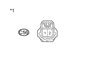
Text in Illustration *1 Front view of wire harness connector
(to E-VRV)
Disconnect the E-VRV connector.
-
Measure the voltage according to the value(s) in the table below.
Standard Voltage Tester Connection Switch Condition Specified Condition C56-1 - Body ground Ignition switch ON 10 to 16 V -
Reconnect the E-VRV connector.
NG
REPAIR OR REPLACE HARNESS OR CONNECTOR Click here
OK
-
-
CHECK HARNESS AND CONNECTOR (E-VRV - ECM)
-
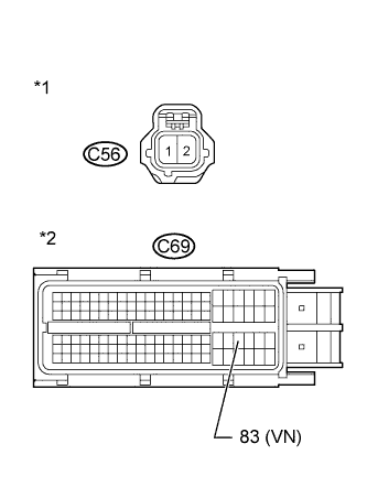
Text in Illustration *1 Front view of wire harness connector
(to E-VRV)
*2 Front view of wire harness connector
(to ECM)
Disconnect the E-VRV connector.
-
Disconnect the ECM connector.
-
Measure the resistance according to the value(s) in the table below.
Standard Resistance (Check for Open) Tester Connection Condition Specified Condition C56-2 - C69-83 (VN) Always Below 1 Ω Standard Resistance (Check for Short) Tester Connection Condition Specified Condition C56-2 or C69-83 (VN) - Body ground Always 10 kΩ or higher -
Reconnect the E-VRV connector.
-
Reconnect the ECM connector.
NG
REPAIR OR REPLACE HARNESS OR CONNECTOR Click here
OK
-
-
REPLACE ECM
-
Replace the ECM Click here.
NEXT
CONFIRM WHETHER MALFUNCTION HAS BEEN SUCCESSFULLY REPAIRED Click here
-
-
REPLACE E-VRV
-
Replace the E-VRV Click here.
NEXT
CONFIRM WHETHER MALFUNCTION HAS BEEN SUCCESSFULLY REPAIRED Click here
-
-
REPAIR OR REPLACE HARNESS OR CONNECTOR
-
Repair or replace the harness or connector.
Tech Tips
If the voltage at the E-VRV connector is not 11 to 14 V, repair or replace the harness and connector between the E-VRV and the EFI MAIN relay (including the EFI No. 2 fuse).
NEXT
-
-
CONFIRM WHETHER MALFUNCTION HAS BEEN SUCCESSFULLY REPAIRED
-
Connect the intelligent tester to the DLC3.
-
Clear the DTCs Click here.
-
Turn the ignition switch to ON for 1 second or more.
-
Enter the following menus: Powertrain / Engine and ECT / DTC.
-
Confirm that the DTC is not output again.
NEXT 
END
-