ECD SYSTEM, Diagnostic DTC:P0031, P0032

| DTC Code | DTC Name |
|---|---|
| P0031 | Oxygen (A/F) Sensor Heater Control Circuit Low (Bank 1 Sensor 1) |
| P0032 | Oxygen (A/F) Sensor Heater Control Circuit High (Bank 1 Sensor 1) |
DESCRIPTION
Tech Tips
-
For more information on the A/F sensor and Diesel Particulate Filter (DPF), refer to the following procedures Click here.
-
This DTC is related to the A/F sensor, although the caption is the oxygen sensor.
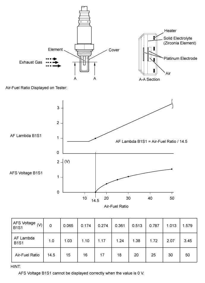
The A/F sensor outputs a voltage* that is proportional to the air-fuel ratio. The A/F sensor output voltage is used to control the A/F mixture.
The A/F sensor is located after the Diesel Particulate Filter (DPF) catalytic converter. This sensor has been developed based on the structure and technology of the A/F sensor that is used for gasoline engine. The cover for the sensor electrode has been modified to suit its application in a diesel engine. This change allows the sensor to function effectively in this DPF type diesel engine, and it also avoids problems with sensor temperature and particulate matter (PM).
In order to reduce PM, the ECM adjusts the air-fuel ratio to a value slightly richer than that which would otherwise be used (note that this mixture is still leaner than the stoichiometric air fuel ratio). The ECM controls these adjustments on signals from the A/F sensor.
When the ECM performs PM forced regeneration (cleaning) by adding fuel using the exhaust fuel addition injector, the A/F sensor feedback is used to ensure that an appropriate air fuel ratio is maintained.
*: This voltage change occurs only inside the ECM. It is not possible to measure this voltage at the sensor. The intelligent tester can be used to monitor this voltage.
Tech Tips
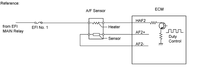
The ECM provides a pulse width modulated control circuit to adjust current through the heater. The A/F sensor heater circuit uses a relay on the +B side of the circuit.
| DTC Detection Drive Pattern | DTC Detection Condition | Trouble Area |
|---|---|---|
|
A/F sensor heater current is 0.8 A or less when the heater operates for 4 seconds. (1 trip detection logic) |
|
| DTC Detection Drive Pattern | DTC Detection Condition | Trouble Area |
|---|---|---|
| Ignition switch ON for 5 seconds | A/F sensor heater current is 0.8 A or more when the heater does not operate for 4 seconds. (1 trip detection logic) |
|
| DTC No. | Data List |
|---|---|
| P0031 |
|
| P0032 |
MONITOR DESCRIPTION
The inner surface of the A/F sensor element is exposed to outside air. The outer surface of the sensor element is exposed to exhaust gases. The sensor element is made of platinum coated zirconia and includes an integrated heating element. The zirconia element generates a small voltage when there is a large difference in the oxygen concentrations of the exhaust and the outside air. The platinum coating amplifies the voltage generation. When heated, the sensor becomes very efficient. If the temperature of the exhaust is low without supplemental heating, the sensor will not generate useful voltage signals. The ECM controls the heating by using a duty-cycle to regulate the average current in the heater element. If the heater current is out of the normal range, the output signals of the sensor are inaccurate and the ECM cannot regulate the air-fuel ratio properly. When the heater current is out of the normal operating range, the ECM interprets this as a malfunction and stores a DTC.
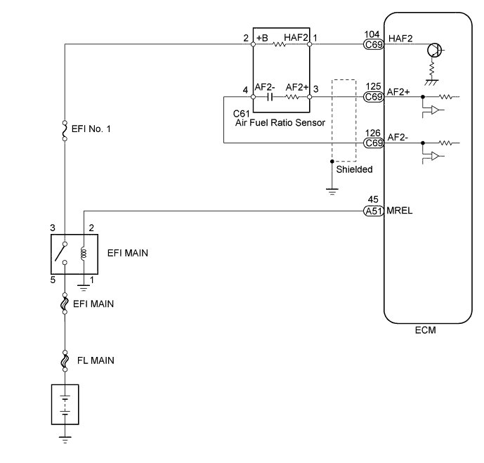
WIRING DIAGRAM
INSPECTION PROCEDURE
Note
-
Inspect the fuses of circuits related to this system before performing the following inspection procedure.
-
After replacing the ECM, the new ECM needs registration Click here and initialization Click here.
PROCEDURE
-
INSPECT AIR FUEL RATIO SENSOR (HEATER RESISTANCE)
-
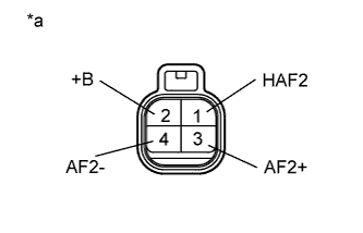
Text in Illustration *a Component without harness connected
(Air Fuel Ratio Sensor)
Disconnect the A/F sensor connector.
-
Measure the resistance between the terminals of the A/F sensor.
Standard Resistance Tester Connection Condition Specified Condition 1 (HAF2) - 2 (+B) 20°C (68°F) 1.8 to 3.4 Ω -
Reconnect the A/F sensor connector.
NG 
REPLACE AIR FUEL RATIO SENSOR Click here
OK 
-
-
CHECK TERMINAL VOLTAGE (A/F SENSOR HEATER VOLTAGE)
-
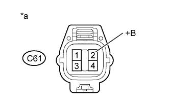
Text in Illustration *a Front view of wire harness connector
(to Air Fuel Ratio Sensor)
Disconnect the air fuel ratio sensor connector.
-
Turn the ignition switch to ON.
-
Measure the voltage according to the value(s) in the table below.
Standard Voltage Tester Connection Switch Condition Specified Condition C61-2 (+B) - Body ground Ignition switch ON 11 to 14 V -
Reconnect the A/F sensor connector.
NG
CHECK HARNESS AND CONNECTOR (A/F SENSOR - EFI MAIN RELAY) Click here
OK
-
-
CHECK HARNESS AND CONNECTOR (A/F SENSOR - ECM)
-
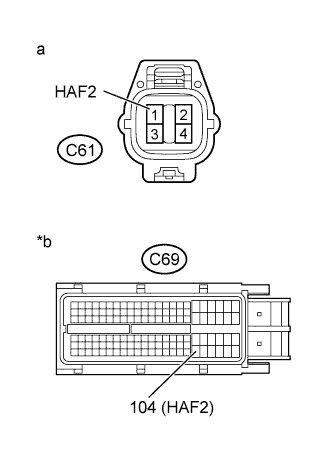
Text in Illustration *a Front view of wire harness connector
(to Air Fuel Ratio Sensor)
*b Front view of wire harness connector
(to ECM)
Disconnect the A/F sensor connector.
-
Disconnect the ECM connector.
-
Measure the resistance according to the value(s) in the table below.
Standard Resistance Tester Connection Condition Specified Condition C61-1 (HAF2) - C69-104 (HAF2) Always Below 1 Ω C61-1 (HAF2) or C69-104 (HAF2) - Body ground Always 10 kΩ or higher -
Reconnect the A/F sensor connector.
-
Reconnect the ECM connector.
NG
REPAIR OR REPLACE HARNESS OR CONNECTOR Click here
OK
-
-
REPLACE ECM
-
Replace the ECM Click here.
NEXT
CONFIRM WHETHER MALFUNCTION HAS BEEN SUCCESSFULLY REPAIRED Click here
-
-
CHECK HARNESS AND CONNECTOR (A/F SENSOR - EFI MAIN RELAY)
-
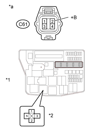
Text in Illustration *1 Engine Room No. 1 Relay Block *2 EFI MAIN relay *a Front view of wire harness connector
(to Air Fuel Ratio Sensor)
Disconnect the A/F sensor connector.
-
Remove the EFI MAIN relay from the engine room No. 1 relay block.
-
Measure the resistance according to the value(s) in the table below.
Standard Resistance Tester Connection Condition Specified Condition C61-2 (+B) - 3 (EFI MAIN relay holder) Always Below 1 Ω C61-2 (+B) or 3 (EFI MAIN relay holder) - Body ground Always 10 kΩ or higher -
Reconnect the A/F sensor connector.
-
Reinstall the EFI MAIN relay.
NG
REPAIR OR REPLACE HARNESS OR CONNECTOR Click here
OK
-
-
CHECK ECM POWER SOURCE CIRCUIT
-
Check the ECM power source circuit Click here.
NEXT
CONFIRM WHETHER MALFUNCTION HAS BEEN SUCCESSFULLY REPAIRED Click here
-
-
REPLACE AIR FUEL RATIO SENSOR
-
Replace the air fuel ratio sensor Click here.
NEXT
CONFIRM WHETHER MALFUNCTION HAS BEEN SUCCESSFULLY REPAIRED Click here
-
-
REPAIR OR REPLACE HARNESS OR CONNECTOR
-
Repair or replace harness or connector.
NEXT
-
-
CONFIRM WHETHER MALFUNCTION HAS BEEN SUCCESSFULLY REPAIRED
-
Connect the intelligent tester to the DLC3.
-
Clear the DTCs Click here.
-
Turn the ignition switch off for 30 seconds or more.
-
Turn the ignition switch to ON.
-
Turn the tester on.
-
Drive the vehicle at 50 km/h (30 mph) or more for a total of 300 seconds or more.
Tech Tips
"Exhaust Temperature B1S1" on the intelligent tester screen should be 200°C (392°F) or higher.
-
Confirm that the DTC is not output again.
Tech Tips
Perform the following procedure using the tester to determine whether or not the DTC judgment has been carried out.
-
Enter the following menus: Powertrain / Engine and ECT / Utility / All Readiness.
-
Input DTC P0031 and/or P0032.
-
Check that STATUS is NORMAL.
Tech Tips
-
If STATUS is NORMAL, DTC judgment is complete and the system is determined to be normal.
-
If STATUS is INCOMPLETE or N/A, DTC judgment is incomplete. Drive the vehicle at 50 km/h (30 mph) or more for a total of 300 seconds or more again.
-
-
NEXT 
END
-