ECD SYSTEM (for CCo) Engine Knocking or Rattling
DESCRIPTION
| Malfunction Condition | Main Trouble Area | Related Trouble Area |
|---|---|---|
| Combustion in diesel engines takes place by means of self-ignition. If the timing of the ignition is delayed, the pressure inside the combustion chamber will increase too fast, which leads to uncontrolled combustion and can be heard as diesel knocking. If any of the following conditions are met, engine knocking may occur due to the fact that
|
|
|
Tech Tips
-
Specified values in the following troubleshooting flowchart are for reference only. Variations in the Data List values may occur depending on the measuring conditions or the vehicle age. Do not judge the vehicle to be normal even when the Data List values indicate a standard level. There are possibly some concealed factors of the malfunction.
-
Check that the vehicle has not been modified in any way prior to the vehicle inspection.
-
Faults and Symptoms of Common Rail Diesel Components
-
Engine Control
Mass Air Flow Meter Component Mass air flow meter Main fault Decrease in performance (foreign matter is stuck) Symptoms Lack of power, black smoke Data List MAF Tech Tips
The maximum fuel injection volume is controlled according to the output from the mass air flow meter.
Glow System Component Glow system Main fault Open circuit, glow plug relay fault Symptoms Difficult to start, rough idle, knocking, white smoke (when cold) Data List Check the glow plug indicator light Diagnostic Point Try to measure the resistance of the glow plug -
Diesel Injection
Fuel Supply Pump Component Fuel supply pump Main fault - Symptoms Difficult to start, engine stalling, rough idle, lack of power Data List Fuel Press, Target Common Rail Pressure, Target Pump SCV Current
-
At a stable condition (e.g. Idling), Fuel Press is within +/-5000 kPa of "Target Common Rail Pressure".
-
If the fuel pressure is 20000 kPa below the target pressure then a lack of power will be felt.
-
If the fuel pressure is below 25000 kPa then idling will be rough.
Tech Tips
-
The fuel pressure changes at engine starting, but is approx. 25000 kPa at engine start after the engine is warmed up.
-
When Target Pump SCV Current is 3000 mA or higher, the suction control valve has a tendency to become stuck.
Diagnostic Trouble Code Even if Fuel Press is less than Target Common Rail Pressure, a DTC will not be stored. Fuel Filter Component Fuel filter Main fault Blockage Symptoms Difficult to start, engine stalling, rough idle, lack of power Data List Fuel Press, Target Common Rail Pressure
-
At a stable condition (e.g. Idling), the fuel pressure is within +/-5000 kPa of "Target Common Rail Pressure".
-
If the fuel pressure is 20000 kPa below the target pressure then a lack of power will be felt.
-
If the fuel pressure is below 25000 kPa then idling will be rough.
Tech Tips
The fuel pressure changes at engine starting, but is approx. 25000 kPa at engine start after the engine is warmed up.
Diagnostic Trouble Code Even if Fuel Press is less than Target Common Rail Pressure, a DTC will not be stored. Fuel Injector Component Fuel injector Main fault Blockage Symptoms Rough idle, lack of power, black smoke, white smoke, knocking Data List Injection Feedback Val
-
When an Injection Feedback Val is more than 3 mm3/st, the cylinder is not normal. This can be read after idling for 1 minute with the engine warmed up (engine coolant temperature is more than 70°C (158°F)).
Injector Driver (EDU) Component Injector Driver (EDU) Main fault Circuit fault: The fuel injector does not open. Symptoms Difficult to start, rough idle, lack of power, black smoke, white smoke, knocking Data List Same as fuel injector Diagnostic Trouble Code When the EDU has a fault, some DTCs may be stored. Fuel Pressure Sensor Component Fuel pressure sensor Main fault Open circuit, Decrease in performance (foreign matter is stuck) Symptoms Difficult to start, rough idle, engine stall, lack of power Data List Fuel Press, Target Common Rail Pressure
-
Slowly raise the engine speed from idling to 3000 rpm with the vehicle stopped, and check that Fuel Press follows Target Common Rail Pressure. If the fuel pressure sensor malfunctions, the actual fuel pressure may deviate from the target fuel pressure (however, the value may not deviate even when a malfunction is present).
Diagnostic Trouble Code When the fuel pressure sensor has a fault, some DTCs may be stored. Irregular Fuel Component Irregular fuel Main fault - Symptoms Difficult to start, rough idle (especially when cold) -
-
Diesel EGR
EGR System Component EGR system Main fault
-
Does not move smoothly
-
Does not close completely
Symptoms
-
Rough idle
-
EGR valve stuck closed: A loud turbocharger sound.
-
EGR valve stuck open: Difficult to start (does not stall), black smoke, lack of power (if there is an excess in the quantity of EGR and there is a heavy load, when the vehicle starts moving, a lack of power will be felt).
Data List Actual EGR Valve Pos., Target EGR Pos.
-
Generally, Actual EGR Valve Pos. = Target EGR Pos. +/-5% (fully closed 0%, fully open 100%).
-
Using EGR valve Active Test, check whether Actual EGR Valve Pos. follows Target EGR Pos. (the engine coolant temperature and intake air temperature should be considered when a malfunction occurs).
-
EGR valve is fully closed when the ignition switch is turned to ON (engine stopped).
-
EGR valve opens to the halfway point at idling after the engine is warmed up.
EGR Close Lrn. Val., EGR Close Lrn. Status
-
When leaving the vehicle idling, when EGR Close Lrn. Status is OK, the normal range of EGR Close Lrn. Val. is 0.34 to 0.70 V.
-
In cases when EGR Close Lrn. Status. is NG or EGR Close Lrn. Val. is out of the normal range (0.34 to 0.70 V), it is possible that the EGR valve cannot completely close.
-
-
Diesel Throttle
Diesel Throttle System Component Diesel throttle system Main fault Stuck, does not move smoothly Symptoms
-
Stuck closed: Lack of power, difficult to start, rough idle, engine stall, black smoke. These may occur when stuck almost fully closed.
-
Stuck open: Turbocharger sound increases. When the engine is stopped, engine vibrations may occur.
Data List
-
Actual Throttle Position
0%: Fully open
100%: Fully closed
-
When the ignition switch is ON (the engine is stopped), the diesel throttle is fully open. When idling, the diesel throttle is at the halfway point. When the ignition switch is turned from ON to off, the throttle is temporarily closed fully.
-
-
-
Data List Related to Knocking
Note
The Data List values in the table are the results of checking one vehicle under a specific condition (engine coolant temperature, intake air temperature, atmospheric pressure etc.). Therefore, use these values for reference only.
-
Engine Control
Engine Speed Data List Judgment of Data List Values Faulty Component Diagnosis Note Engine Speed Idling: 720 to 820 rpm Crankshaft position sensor When the crankshaft position sensor is malfunctioning, "Engine Speed" is approximately 0 or varies greatly from the actual engine speed. MAP Data List Judgment of Data List Values Faulty Component Diagnosis Note MAP
-
When MAP is low, there will be difficulty starting.
-
With ignition switch ON or during idling, MAP is nearly equal to Atmosphere Pressure (standard atmospheric pressure = 101 kPa).
When MAP is low, the following conditions are possible:
-
Diesel throttle nearly fully closed.
-
Intake system blocked (turbocharger system also).
-
Exhaust system blocked.
-
When the ignition switch to ON or the vehicle is idling, MAP (intake manifold absolute pressure) and Atmosphere Pressure are approximately equal (standard atmospheric pressure = 101 kPa).
Above approx. 1500 rpm, the turbo becomes effective, and the pressure becomes higher than atmospheric pressure.
-
Inspect while comparing with "Target Booster Pressure".
-
With the accelerator fully open, if the actual Manifold Absolute Pressure (MAP) is low compared to the target booster pressure by at least 20 kPa for 5 seconds or more, a feeling of insufficient power will occur.
Results of real-vehicle check:
-
Ignition switch ON: 100 kPa
-
Cranking: 99 kPa
-
Idling (warm up the engine): 90 kPa (2 minutes after starting the vehicle)
-
Running without load (2500 rpm): 101 kPa
-
Driving with the accelerator fully open at 2000 rpm: 199 kPa
-
Driving with the accelerator fully open at 3000 rpm: 228 kPa
MAF Data List Judgment of Data List Values Faulty Component Diagnosis Note MAF -
-
MAF meter
-
MAF meter circuit
-
Intake system clogging, leaking
-
Exhaust system clogging
-
Turbocharger sub-assembly
-
Leaking or clogging of turbocharger passages
-
EGR valve does not close
-
Based on the MAF, the ECM controls the fuel injection volume, injection timing, EGR, etc.
-
If the value is always approximately 0 g/sec.:
-
Mass air flow meter power source circuit is open.
-
VG circuit is open or shorted.
-
EVG circuit is open.
Results of real-vehicle check:
-
Ignition switch ON: 0 g/sec.
-
Cranking: 4.04 g/sec.
-
Idling (warm up the engine): 8.21 g/sec. (2 minutes after starting the vehicle)
-
Running without load (2500 rpm): 41 g/sec.
-
Driving with the accelerator fully open at 2000 rpm: 74 g/sec.
-
Driving with the accelerator fully open at 3000 rpm: 119 g/sec.
Tech Tips
The maximum fuel injection volume is controlled according to the output from the mass air flow meter.
Intake Air Data List Judgment of Data List Values Faulty Component Diagnosis Note Intake Air - Intake air temperature sensor.
-
After a long soak, the engine coolant temperature, intake air temperature and ambient air temperature are approximately equal.
-
If the value is -40°C (-40°F) or 140°C (284°F), the sensor circuit is open or shorted.
Coolant Temp Data List Judgment of Data List Values Faulty Component Diagnosis Note Coolant Temp
-
Engine coolant temperature is approximately equal to intake air temperature after leaving overnight. After warm-up: Engine coolant temperature is 70°C (158°F) or more.
-
In cases when the engine coolant temperature output is obviously higher than the actual engine coolant temperature, when it is cold, there will be difficulty starting due to problems with glow plugs or insufficient fuel injection.
-
In cases when the engine coolant temperature sensor output is obviously lower than the actual engine coolant temperature, when it is warm, there will be difficulty starting (black smoke will also occur) due to an excess of injected fuel.
Engine coolant temperature sensor
-
If the value is -40°C (-40°F) or 140°C (284°F), the sensor circuit is open or shorted.
-
After a long soak, the coolant temperature, intake air temperature and ambient air temperature are approximately equal.
Engine Speed of Cyl #1 (to #4) Data List Judgment of Data List Values Faulty Component Diagnosis Note Engine Speed of Cyl #1 (to #4) When cranking, the engine speed of each cylinder is the same under normal conditions. When a cylinder is approximately 100 rpm higher than the other cylinders, it is conceivable that the compression of that cylinder is being lost.
Tech Tips
This data is output only when the Active Test "Check the Cylinder Compression" is performed.
-
-
Output only when the Active Test "Check the Cylinder Compression" is performed.
-
With this Active Test, the fuel injection is stopped.
-
Indicates the speed of each cylinder when cranking.
Example - Normal: "Engine speed" of all cylinders is approximately equal.
No. 1 cylinder compression low: "Engine speed of Cyl#1" = approximately 300 rpm, "Engine speed of Cyl #2 to #4 cylinder" = approximately 200 rpm.
-
-
Diesel Injection
Target Common Rail Pressure Data List Judgment of Data List Values Faulty Component Diagnosis Note Target Common Rail Pressure - -
-
Inspect the (actual) fuel pressure, comparing it against the common rail target value.
-
Considered normal when the actual fuel pressure is within +/-5000 kPa of the target fuel pressure under stable conditions.
Results of real-vehicle check:
-
Ignition switch ON: 36000 kPa
-
Cranking: 40000 kPa
-
Idling (warm up the engine): 32000 kPa (2 minutes after starting the vehicle)
-
Running without load (2500 rpm): 41410 kPa
-
Running without load (3500 rpm): 70140 kPa
-
Driving with the accelerator fully open at 2000 rpm: 149780 kPa
-
Driving with the accelerator fully open at 3000 rpm: 184720 kPa
Fuel Press Data List Judgment of Data List Values Faulty Component Diagnosis Note Fuel Press
-
In a stable operating condition (e.g. idling), Fuel Press is Target Common Rail Pressure +/-5000 kPa.
-
During cranking, if Fuel Press is lower than 25000 kPa, there may be difficulty starting (take care as there is a response lag when the pressure rises).
-
When Fuel Press is lower than 25000 kPa, rough idling will occur.
-
If there is a fault with the fuel supply pump (lack of discharge quantity) or pressure discharge valve (will not fully close), the fuel pressure will drop. Also, a blocked fuel filter, leakage from fuel pipes, and lack of fuel will also make the fuel pressure drop.
-
If air mixes with the fuel, the fuel pressure will shift away from the target fuel pressure.
-
When there is a fault with the fuel supply pump, there is a possibility of lack of power, engine stall, rough idle and difficulty starting.
-
Fuel press is the actual common rail fuel pressure.
-
Inspect by comparing Fuel Press with Target Common Rail Pressure.
-
The ECM uses Fuel Press for feedback control of Target Fuel Pressure via the supply pump.
The injection amount is determined based on the injection timing and fuel pressure.
Also, the spray pattern is selected based on the fuel pressure.
Results of real-vehicle check:
-
Ignition switch ON: 0 kPa
-
Cranking: 19350 kPa
-
Idling (warm up the engine): 32000 kPa (2 minutes after starting the vehicle)
-
Running without load (2500 rpm): 39920 kPa
-
Driving with the accelerator fully open at 2000 rpm: 146600 kPa
-
Driving with the accelerator fully open at 3000 rpm: 176230 kPa
Target Pump SCV Current Data List Judgment of Data List Values Faulty Component Diagnosis Note Target Pump SCV Current Idling after warming up: roughly 923 to 1123 mA. When this value is large, the pump is trying to increase the fuel discharge rate.
-
With this data, component fault not specified, use this data as a reference.
-
If the current is 3000 mA or more, there is a possibility the suction control valve is stuck.
-
ECU-calculated value for the suction control valve actuation target current.
-
Value is large when a high fuel pressure is desired.
-
When this deviates from the standard value, it indicates that for some reason, even though the pump is running hard, the actual fuel pressure is inconsistent with the target fuel pressure.
Results of real-vehicle check:
-
Ignition switch ON: 998.7 mA
-
Cranking: 1165 mA
-
Running without load (2500 rpm): 1018 mA
-
Driving with the accelerator fully open at 2000 rpm: 1205 mA
-
Driving with the accelerator fully open at 3000 rpm: 1280 mA
Injection Feedback Val #1 (to #4) Data List Judgment of Data List Values Faulty Component Diagnosis Note Injection Feedback Val #1 (to #4)
-
When idling after the engine is warmed up, the fuel quantity of each fuel injector is corrected to make each cylinder engine speed equal.
-
Cylinders more than 3 mm3/st may have a fault.
Tech Tips
Read the value after one minute of idling after warm up (engine coolant temperature above 70°C (158°F)). This value is only calculated when idling.
-
Fault with a fuel injector or lack of compression of a cylinder with a large Injection Feedback Val.
-
Do a compression Active Test. If there is a cylinder that is around 100 rpm more than the other cylinders, there is a possibility that the compression of that cylinder is being lost.
-
If all the cylinder speeds are even according to the compression Active Test result, the fuel injector of the cylinder may have a fault.
-
With fuel injector faults, other than difficulty starting, there is a possibility of rough idling, lack of power, black smoke, white smoke and knocking.
-
When idling after warm up, the injection amount for each cylinder is corrected to optimize the difference of each cylinder engine speed.
Example: For cylinders that are slowing the engine speed compared to other cylinders, the injection volume is increased.
-
"Injection Feedback Val" more than 3.0 mm3/st: Injector breakdown or insufficient compression is causing poor combustion.
Injection Volume Data List Judgment of Data List Values Faulty Component Diagnosis Note Injection Volume - - After warming up the engine, when Injection Volume during idling is 10 mm3/st or more, there is tendency for the injector to clog.
Results of real-vehicle check:
-
Cranking: 22 mm3/st (Note: Varies depending on coolant temperature)
-
Idling (warm up the engine): 5.8 mm3/st
-
Running without load (2500 rpm): 5.0 mm3/st
-
Running without load (4700 rpm): 8.7 mm3/st
-
Driving with the accelerator fully open at 2000 rpm: 68 mm3/st
-
Driving with the accelerator fully open at 3000 rpm: 61 mm3/st
Pilot 1 Injection Period Tester Display Judgment of Data List Values Faulty Component Diagnosis Note Pilot 1 Injection Period - - Check to see if "Pilot 1 Injection Period" is not zero when symptoms occur. Results of real-vehicle check:
-
Cranking: 386 μs
-
Idling (warm up the engine): 241 μs
-
Running without load (2500 rpm): 0 μs
-
Running without load (3500 rpm): 0 μs
-
Driving with the accelerator fully open at 2000 rpm: 0 μs
-
Driving with the accelerator fully open at 3000 rpm: 0 μs
Pilot 2 Injection Period Tester Display Judgment of Data List Values Faulty Component Diagnosis Note Pilot 2 Injection Period - - Check to see if "Pilot 2 Injection Period" is not zero when symptoms occur. Results of real-vehicle check:
-
Ignition switch ON: 0 μs
-
Cranking: 600 μs
-
Idling (warm up the engine): 245 μs (2 minutes after starting the vehicle)
-
Running without load (2500 rpm): 211 μs
-
Driving with the accelerator fully open at 2000 rpm: 156 μs
-
Driving with the accelerator fully open at 3000 rpm: 157 μs
Main Injection Period Tester Display Judgment of Data List Values Faulty Component Diagnosis Note Main Injection Period - -
-
When the fuel pressure becomes 15000 kPa or less, "Main Injection Period" is set to 0.
-
When the engine will not start, confirm that injection is performed.
-
When P0093, P0627 or P062D is stored, there is an engine stall request. At that time, "Main Injection Period" equals 0.
Tech Tips
As the engine stalls 1 minute after the MIL illuminates, freeze frame data cannot be checked.
Results of real-vehicle check:
-
Cranking: 904 μs
-
Idling (warm up the engine): 292 μs (2 minutes after starting the vehicle)
-
Running without load (2500 rpm): 244 μs
-
Driving with the accelerator fully open at 2000 rpm: 789 μs
-
Driving with the accelerator fully open at 3000 rpm: 619 μs
-
-
Diesel Throttle
Actual Throttle Position Data List Judgment of Data List Values Faulty Component Diagnosis Note Actual Throttle Position
-
When the ignition switch is turned to ON (engine stopped), the diesel throttle is fully open. When the ignition switch is turned from ON to off, the diesel throttle is fully closed temporarily.
-
With the diesel throttle stuck almost fully closed, there is a possibility of rough idling, engine stall, black smoke, difficulty starting and lack of power.
Diesel throttle body Actual Throttle Position is the closing percentage of the throttle valve.
-
Fully closed: 100%
-
Fully open: 0%
Tech Tips
There is no connection with the accelerator. However, under full load, the throttle is usually fully open (0%).
Results of real-vehicle check:
-
Ignition switch ON: 0%
-
Cranking: -9%
-
Idling (warm up the engine): 89%
-
Running without load (2500 rpm): 76%
-
Driving with the accelerator fully open at 2000 rpm: 0%
-
Driving with the accelerator fully open at 3000 rpm: 0%
-
-
Diesel EGR
Target EGR Position Data List Judgment of Data List Values Faulty Component Diagnosis Note Target EGR Position - -
-
Fully open: 100%
-
Fully closed: 0%
-
Used for comparison to "Actual EGR Valve Pos".
Results of real-vehicle check:
-
Ignition switch ON: 0%
-
Cranking: 0%
-
Idling (warm up the engine): 35%
-
Running without load (2500 rpm): 0%
-
Driving with the accelerator fully open at 2000 rpm: 0%
-
Driving with the accelerator fully open at 3000 rpm: 0%
Actual EGR Valve Pos. Data List Judgment of Data List Values Faulty Component Diagnosis Note Actual EGR Valve Pos.
-
Generally Actual EGR Valve Pos. = Target EGR Pos. (Fully closed = 0%, Fully open = 100%)
-
The EGR valve Active Test can be used to check whether the Actual EGR Valve Pos. = Target EGR Pos.
EGR valve assembly
-
Inspect while comparing to "Target EGR Valve Pos.".
-
Sometimes the malfunction only occurs around a certain temperature, so refer to the engine coolant temperature and outside temperature at the time the malfunction occurred.
Results of real-vehicle check:
-
Ignition switch ON: 0%
-
Cranking: 0%
-
Idling (warm up the engine): 35%
-
Running without load (2500 rpm): 0%
-
Driving with the accelerator fully open at 2000 rpm: 0%
-
Driving with the accelerator fully open at 3000 rpm: 0%
EGR Close Lrn. Status Data List Judgment of Data List Values Faulty Component Diagnosis Note EGR Close Lrn. Status
-
"OK" means the fully closed position learning has completed normally.
-
When NG, the learned fully closed position may be outside of the normal range.
- After disconnecting and reconnecting the battery cable, if the ignition switch has not been turned off once, learning may not be completed. EGR Close Lrn. Val. Data List Judgment of Data List Values Faulty Component Diagnosis Note EGR Close Lrn. Val. When leaving the vehicle idling, with the EGR Close Lrn. Status OK, the normal range of EGR Close Lrn. Val. is within 0.34 to 0.70 V. In cases when EGR Close Lrn. Status is NG or EGR Close Lrn. Val. is at the maximum or minimum (0.34 to 0.70 V) of the normal range, it is possible that the EGR valve is not completely closed or a foreign object is lodged in the EGR valve seat area. -
-
This value is the EGR position sensor output voltage.
-
As the maximum and minimum settings are 0.34 V and 0.70 V, if the value becomes stuck at either of these, there is a malfunction in the lift sensor or the valve position is shifted (due to foreign matter, etc.).
-
-
INSPECTION PROCEDURE
Note
-
After replacing the fuel supply pump, the ECM needs initialization Click here.
-
After replacing a fuel injector, the ECM needs registration Click here.
Tech Tips
-
This troubleshooting procedure checks for knocking and rattling.
-
Knocking is most likely to occur while the engine is idling.
-
Explanation of Symptom
Engine knocking or rattling Combustion in diesel engines takes place by means of self-ignition. If the timing of the ignition is delayed, the pressure inside the combustion chamber will increase too fast, which leads to uncontrolled combustion and can be heard as diesel knocking.
If one of the following conditions is met, engine knocking may occur due to the fact that
-
The diesel fuel self ignition timing takes place too late
-
The engine temperature is low
-
The intake air temperature is low
-
The self-ignition temperature of the diesel fuel is high (e.g., low cetane number)
-
Fuel is injected into a cold combustion chamber (compression temperature is too low)
-
There is inadequate fuel vaporization (air-fuel mixture formation is unsatisfactory)
-
There is pilot injection deterioration due to an injector sticking or contamination
-
PROCEDURE
-
CHECK SOUND AREA
-
Find the source of the abnormal sound using a mechanic's stethoscope.
Result Result Proceed to Sound from supply pump A Sound from parts other than supply pump B
B 
REPAIR OR REPLACE MALFUNCTIONING PARTS
A 
-
-
CHECK WIRE HARNESS IN ENGINE COMPARTMENT
-
Check the harness and connector connections of common rail system components.
OK The wire harnesses and connectors are connected securely.
NG
REPAIR OR REPLACE HARNESS OR CONNECTOR
OK
-
-
CHECK AIR INDUCTION SYSTEM (PROCEDURE 3)
-
Check the air induction system (turbocharger, MAP sensor, EGR valve, etc.).
OK All hoses are connected securely and there are no leaks or blockage in the air induction system.
NG
REPAIR OR REPLACE AIR INDUCTION SYSTEM
OK
-
-
READ OUTPUT DTCS (RELATING TO ENGINE)
-
Connect the intelligent tester to the DLC3.
-
Turn the ignition switch to ON and turn the tester on.
-
Enter the following menus: Powertrain / Engine and ECT / DTC.
-
Read DTCs.
Result Result Proceed to No output A Engine related DTCs B
B
GO TO DTC CHART Click here
A
-
-
READ VALUE USING INTELLIGENT TESTER (MAP AND ATMOSPHERE PRESSURE)
-
Connect the intelligent tester to the DLC3.
-
Turn the ignition switch to ON and turn the tester on.
-
Enter the following menus: Powertrain / Engine and ECT / Data List / MAP and Atmosphere Pressure.
-
Compare MAP to Atmosphere Pressure when the ignition switch is ON (do not start the engine).
Standard Difference between MAP and Atmosphere Pressure is less than 8 kPa. Tech Tips
-
If MAP and Atmosphere Pressure have the same value, both are normal. If there is a difference of 8 kPa or more, compare the values to the atmospheric pressure for that day. The sensor whose deviation is the greatest is malfunctioning.
-
Standard atmospheric pressure is 101 kPa. For every 100 m increase in altitude, pressure drops by 1 kPa. Varies by weather.
Result Result Proceed to MAP and Atmosphere Pressure have the same value A MAP is different from actual atmospheric pressure B Atmosphere Pressure is different from actual atmospheric pressure C -
B
REPLACE MANIFOLD ABSOLUTE PRESSURE SENSOR Click here
C
REPLACE ECM Click here
A
-
-
PERFORM ACTIVE TEST USING INTELLIGENT TESTER (FUEL LEAK TEST)
Tech Tips
By performing this Active Test, the engine speed is maintained at high RPM and the common rail internal fuel pressure is raised to the maximum operating pressure. As a result, a fuel leak check can be conducted while retaining the high common rail pressure.
-
Connect the intelligent tester to the DLC3.
-
Turn the ignition switch to ON and turn the tester on.
-
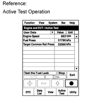
Enter the following menus: Powertrain / Engine and ECT/ Active Test / Test the Fuel Leak / Data List / Fuel Press, Target Common Rail Pressure, and Target Pump SCV Current.
-
Take a snapshot with the intelligent tester during the Active Test.
Tech Tips
Detailed graphs can be displayed by transferring the stored snapshot from the tester to a PC (personal computer) with Intelligent Viewer installed.
-
Measure the difference between the target fuel pressure (Target Common Rail Pressure) and the actual fuel pressure (Fuel Press) when the "Test the Fuel Leak" Active Test is performed.
Tech Tips
In order to obtain an exact measurement, perform the Active Test 5 times and measure the difference once each time the Active Test is performed.
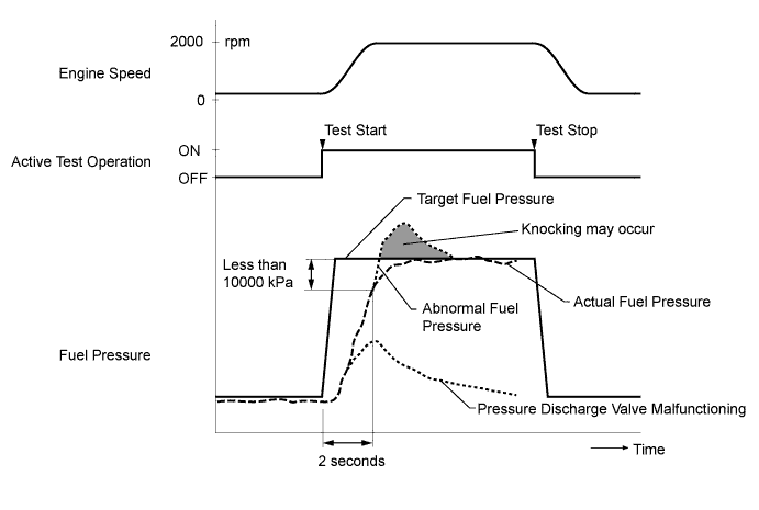
OK The difference between the target fuel pressure and the actual fuel pressure 2 seconds after the Active Test starts is less than 10000 kPa. Tech Tips
-
Target Common Rail Pressure means the target fuel pressure controlled by the ECM.
-
Fuel Press means the actual fuel pressure.
-
If the pressure discharge valve mounted on the common rail is malfunctioning, the actual fuel pressure will change as indicated by "Pressure Discharge Valve Malfunctioning" in the illustration.
-
If the pump is controlled using the Active Test "Test the Fuel Leak", when the Active Test is stopped, the actual fuel pressure may drop below the target common rail pressure, but this is normal and does not indicate a malfunction.
-
-
Read the value of Target Pump SCV Current in the Data List when the "Test the Fuel Leak" Active Test is performed.
Standard Target Pump SCV Current is between 800 mA and 3000 mA. Tech Tips
If the value of Target Pump SCV Current stored in the snapshot is higher than the standard, the intermittent suction control valve is probably stuck.
Result Result Proceed to Both results are within standard A Fuel pressure exceeds "Target Common Rail Pressure + 10000 kPa"
and/or
Target Pump SCV Current value is out of standard range
B Fuel pressure does not reach "Target Common Rail Pressure - 10000 kPa" within 2 seconds C
B 
CHECK HARNESS AND CONNECTOR (SUCTION CONTROL VALVE - ECM) Click here
C
BLEED AIR FROM FUEL SYSTEM Click here
A
-
-
CHECK INJECTOR COMPENSATION CODE
Note
Injector compensation codes are unique, 30-digit, alphanumeric values printed on the head portion of each injector. If an incorrect injector compensation code is input into the ECM, the engine may rattle or engine idling may become rough. In addition, engine failure may occur and the life of the engine may be shortened.
-
Check the injector compensation codes Click here.
OK Compensation codes of the installed injectors are the same as the compensation codes registered in the ECM.
NG
REGISTER INJECTOR COMPENSATION CODE AND PERFORM PILOT QUANTITY LEARNING Click here
OK
-
-
RESET ECM
-
Disconnect the cable from the negative (-) battery terminal for at least 2 minutes.
-
Reconnect the cable to the negative (-) battery terminal.
-
Check whether the malfunction has been successfully repaired.
OK Malfunction has been repaired successfully.
NG
READ VALUE USING INTELLIGENT TESTER (CONTROL THE EGR STEP POSITION) Click here
OK 
END
-
-
READ VALUE USING INTELLIGENT TESTER (CONTROL THE EGR STEP POSITION)
-
Turn the ignition switch to ON.
-
Turn the ignition switch off and wait for 15 seconds or more.
-
Connect the intelligent tester to the DLC3.
-
Turn the ignition switch to ON and turn the tester on.
-
Enter the following menus: Powertrain / Engine and ECT / Active Test / Control the EGR Step Position / Data List / Actual EGR Valve Pos..
-
Start the engine.
-
When closing the EGR valve using the Control the EGR Step Position Active Test check that Actual EGR Valve Pos. smoothly changes to the set opening angle.
OK Value smoothly changes to set opening angle. Tech Tips
Under normal conditions, Actual EGR Valve Pos. is indicated as follows.
EGR Valve Condition Actual EGR Valve Pos. Fully closed 0% Fully open About 100%
NG
REPLACE EGR VALVE ASSEMBLY Click here
OK
-
-
READ VALUE USING INTELLIGENT TESTER (EGR CLOSE LRN. VAL. AND EGR CLOSE LRN. STATUS)
-
Turn the ignition switch to ON.
-
Turn the ignition switch off and wait for 15 seconds or more.
-
Connect the intelligent tester to the DLC3.
-
Turn the ignition switch to ON and turn the tester on.
-
Enter the following menus: Powertrain / Engine and ECT/ Data List / EGR Close Lrn. Val. and EGR Close Lrn. Status.
-
Read the values.
Standard EGR Close Lrn. Status is OK Tech Tips
-
When EGR Close Lrn. Status is NG, the value of the EGR Close Lrn. Val. is unavailable because the EGR fully closed learned value is out of the standard range.
-
When EGR Close Lrn. Status is NG, the ECM suspends the learned value update. The value indicated on the tester is the past data when the EGR valve worked properly or the initialized data remaining from when the battery cable was reconnected, i.e., the value is not current data.
-
As the EGR valve opens, the sensor output voltage decreases.
-
If the amount of EGR is insufficient, engine knocking may occur.
-
NG
INSPECT EGR VALVE ASSEMBLY Click here
OK
-
-
INSPECT DIESEL THROTTLE BODY ASSEMBLY
-
Connect the intelligent tester to the DLC3.
-
Turn the ignition switch to ON and turn the tester on.
-
Enter the following menus: Powertrain / Engine and ECT / Active Test / Diesel Throttle Target Angle.
-
When changing the Active Test continuously value to 0, 30, 60, 90, 60, 30 and 0%, check that Actual Throttle Position smoothly changes to the set opening angle.
OK Value smoothly changes to set opening angle.
NG
REPLACE DIESEL THROTTLE BODY ASSEMBLY Click here
OK
-
-
CHECK THE TEMPERATURE WHEN KNOCKING OCCURS
-
Check the temperature when knocking trouble occurs.
Result Result Proceed to Knocking only for cold engine A Knocking both for cold and warmed up engine B
B
READ VALUE USING INTELLIGENT TESTER (MAP AND MAF) Click here
A
-
-
INSPECT ENGINE COOLANT TEMPERATURE SENSOR
-
After warming up the engine, the engine coolant temperature should be 70°C (158°F) or more. After leaving the vehicle overnight, the engine coolant temperature should be nearly equal to the intake air temperature.
OK The engine coolant temperature is nearly equal to the intake air temperature. Tech Tips
If the engine coolant temperature sensor output is less than the actual engine coolant temperature, engine knocking may occur.
NG
REPLACE ENGINE COOLANT TEMPERATURE SENSOR Click here
OK
-
-
INSPECT GLOW PLUG ASSEMBLY (RESISTANCE)
-
Disconnect the glow plug connector.
-
Measure the resistance according to the value(s) in the table below.
Standard Resistance Tester Connection Condition Specified Condition Glow plug terminal - Body ground 20°C (68°F) Approximately 1.0 Ω Tech Tips
If any of the glow plugs has an open circuit, the engine power will be insufficient only when the engine is cold.
Note
-
Exercise extreme care not to damage the glow plug pipes. Damaging them could cause an open circuit or shorten the life of the glow plugs.
-
Keep the glow plugs free of oil and fuel while cleaning.
-
Wipe any oil off of the terminal and Bakelite washer with a clean, dry cloth during inspection.
-
Do not apply more than 11 V to the glow plugs as it may cause an open circuit.
-
-
Reconnect the glow plug connector.
NG
REPLACE GLOW PLUG ASSEMBLY Click here
OK
-
-
READ VALUE USING INTELLIGENT TESTER (MAP AND MAF)
-
Connect the intelligent tester to the DLC3.
-
Start the engine, warm it up, and then turn the tester on.
-
Enter the following menus: Powertrain / Engine and ECT / Data List / MAP and MAF.
Standard Item Engine Speed*1 Standard Range Description MAP*2 Ignition switch ON (engine stopped) Same as atmospheric pressure Intake manifold internal pressure detected by manifold absolute pressure sensor Idling 90 to 100 kPa (675 to 750 mmHg, 26.57 to 29.53 in.Hg) 3000 rpm (no engine load) 100 to 150 kPa (750 to 1125 mmHg, 29.53 to 44.29 in.Hg) MAF*2, *3 Ignition switch ON (engine stopped) Less than 0.5 g/s Intake air volume detected by mass air flow meter Idling 3 to 12 g/s 2000 rpm (no engine load) 14 to 130 g/s Result Item Result Proceed to MAP and MAF Within standard range A MAP and MAF Outside standard range B Only MAP Outside standard range C Only MAF Outside standard range D Tech Tips
*1: The A/C switch and all accessory switches should be off with a fully warm engine.
*2: This value is indicated when the ambient temperature is 25°C (77°F) and the atmospheric pressure is 101 kPa (758 mmHg, 29.83 in.Hg), and a stable boost pressure is maintained for approximately 10 seconds.
*3: When the mass air flow meter malfunctions, the MAF output may deviate from the standard (referential) range when the engine idles and is accelerated from 3000 to 4000 rpm with full throttle acceleration.
B
CHECK AIR INDUCTION SYSTEM (PROCEDURE 3)
C
GO TO DTC P0107 AND P0108 (RELATED TO MANIFOLD PRESSURE SENSOR) Click here
D
GO TO DTC P0102 AND P0103 (RELATED TO MASS AIR FLOW METER) Click here
A
-
-
INSPECT EGR VALVE ASSEMBLY
-
Remove the EGR valve assembly Click here.
-
Check that the EGR valve fully closes.
OK The EGR valve fully closes. Tech Tips
-
Hold the EGR valve to a light and confirm that the valve contacts the valve seat securely.
-
If light leaks out from the valve, the EGR valve is not fully closed.
-
Remove the deposits if there are many deposits in the EGR valve or the passage of the intake manifold.
-
-
Install the EGR valve assembly Click here.
NG
REPLACE EGR VALVE ASSEMBLY Click here
OK
-
-
BASIC INSPECTION
-
Check the fuel quality.
-
Check the fuel for air.
-
Check the fuel system for blockages.
-
Check the air filter.
-
Check the engine oil.
-
Check the engine idling speed and maximum engine speed.
-
Check the vacuum pump.
NG
REPAIR OR REPLACE MALFUNCTIONING PARTS
OK
-
-
CONFIRM WHETHER MALFUNCTION HAS BEEN SUCCESSFULLY REPAIRED
-
Check whether the knocking has been successfully repaired.
NG
READ VALUE USING INTELLIGENT TESTER (INJECTION VOLUME AND INJECTOR) Click here
OK
END
-
-
READ VALUE USING INTELLIGENT TESTER (INJECTION VOLUME AND INJECTOR)
-
Connect the intelligent tester to the DLC3.
-
Start the engine and warm it up until the engine coolant temperature reaches 75°C (167°F) or higher.
-
Allow the engine to idle for 1 minute or more.
Tech Tips
The A/C switch and all accessory switches should be off with a fully warm engine.
-
Turn the tester on.
-
Enter the following menus: Powertrain / Engine and ECT / Data List / Injection Volume and Injector Feedback Val. #1 to #4.
-
Read the values during engine idling.
Standard Tester Display Condition Specified Condition Injection Volume Idling Less than 10.0 mm3/st
Injector Feedback Val. #1
Injector Feedback Val. #2
Injector Feedback Val. #3
Injector Feedback Val. #4
Idling Between -3.0 and 3.0 mm3/st
Note
If any Injector Feedback Val. is out of the specified range, replace all of the fuel injectors together.
NG
REPLACE FUEL INJECTOR Click here
OK
END
-
-
BLEED AIR FROM FUEL SYSTEM
-
Bleed the air from the fuel system Click here.
NEXT
-
-
PERFORM ACTIVE TEST USING INTELLIGENT TESTER (FUEL LEAK TEST)
Tech Tips
By performing this Active Test, the engine speed is maintained at high RPM and the common rail internal fuel pressure is raised to the maximum operating pressure. As a result, a fuel leak check can be conducted while retaining the high common rail pressure.
-
Connect the intelligent tester to the DLC3.
-
Turn the ignition switch to ON and turn the tester on.
-
Enter the following menus: Powertrain / Engine and ECT/ Active Test / Test the Fuel Leak / Data List / Fuel Press, Target Common Rail Pressure, and Target Pump SCV Current.
-
Take a snapshot with the intelligent tester during the Active Test.
Tech Tips
Detailed graphs can be displayed by transferring the stored snapshot from the tester to a PC (personal computer) with Intelligent Viewer installed.
-
Measure the difference between the target fuel pressure (Target Common Rail Pressure) and the actual fuel pressure (Fuel Press) when the "Test the Fuel Leak" Active Test is performed.
Tech Tips
In order to obtain an exact measurement, perform the Active Test 5 times and measure the difference once each time the Active Test is performed.
OK The difference between the target fuel pressure and the actual fuel pressure 2 seconds after the Active Test starts is less than 10000 kPa. Tech Tips
-
Target Common Rail Pressure means the target fuel pressure controlled by the ECM.
-
Fuel Press means the actual fuel pressure.
-
If the pressure discharge valve mounted on the common rail is malfunctioning, the actual fuel pressure will change as indicated by "Pressure Discharge Valve Malfunctioning" in the illustration.
-
If the pump is controlled using the Active Test "Test the Fuel Leak", when the Active Test is stopped, the actual fuel pressure may drop below the target common rail pressure, but this is normal and does not indicate a malfunction.
-
NG
CONFIRM IF FUEL BEING SUPPLIED TO FUEL SUPPLY PUMP Click here
OK
-
-
CONFIRM WHETHER MALFUNCTION HAS BEEN SUCCESSFULLY REPAIRED
-
Check whether the knocking has been successfully repaired.
NEXT
END
-
-
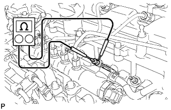
CHECK HARNESS AND CONNECTOR (SUCTION CONTROL VALVE - ECM)
-
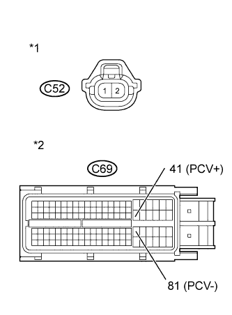
Text in Illustration *1 Front view of wire harness connector
(to Suction Control Valve)
*2 Front view of wire harness connector
(to ECM)
Disconnect the suction control valve connector.
-
Disconnect the ECM connector.
-
Measure the resistance according to the value(s) in the table below.
Standard Resistance (Check for Open) Tester Connection Condition Specified Condition C52-1 (+B) - C69-41 (PCV+) Always Below 1 Ω C52-2 (PCV) - C69-81 (PCV-) Always Below 1 Ω Standard Resistance (Check for Short) Tester Connection Condition Specified Condition C52-1 (+B) or C69-41 (PCV+) - Body ground Always 10 kΩ or higher C52-2 (PCV) or C69-81 (PCV-) - Body ground Always 10 kΩ or higher -
Reconnect the suction control valve connector.
-
Reconnect the ECM connector.
NG
REPAIR OR REPLACE HARNESS OR CONNECTOR
OK
-
-
CONFIRM IF FUEL BEING SUPPLIED TO FUEL SUPPLY PUMP
-
Disconnect the inlet hose from the fuel supply pump.
-
Operate the priming pump and check that fuel is being supplied to the fuel supply pump.
OK Fuel is properly supplied to the fuel supply pump when the priming pump is operated. Tech Tips
-
When there is a lack of fuel, fuel pressure drops.
-
Check that the fuel filter is not clogged.
-
NG
REPAIR OR REPLACE FUEL FILTER OR CLOGGED FUEL PIPE (INCLUDING FUEL FREEZING, FUEL TANK - FUEL SUPPLY PUMP)
OK
-
-
REPLACE SUCTION CONTROL VALVE
-
Replace the suction control valve Click here.
NEXT
-
-
BLEED AIR FROM FUEL SYSTEM
-
Bleed the air from the fuel system Click here.
NEXT
-
-
PERFORM FUEL SUPPLY PUMP INITIALIZATION
-
Perform fuel supply pump initialization Click here.
NEXT
-
-
PERFORM ACTIVE TEST USING INTELLIGENT TESTER (FUEL LEAK TEST)
Tech Tips
By performing this Active Test, the engine speed is maintained at high RPM and the common rail internal fuel pressure is raised to the maximum operating pressure. As a result, a fuel leak check can be conducted while retaining the high common rail pressure.
-
Connect the intelligent tester to the DLC3.
-
Turn the ignition switch to ON and turn the tester on.
-
Enter the following menus: Powertrain / Engine and ECT/ Active Test / Test the Fuel Leak / Data List / Fuel Press, Target Common Rail Pressure, and Target Pump SCV Current.
-
Take a snapshot with the intelligent tester during the Active Test.
Tech Tips
Detailed graphs can be displayed by transferring the stored snapshot from the tester to a PC (personal computer) with Intelligent Viewer installed.
-
Measure the difference between the target fuel pressure (Target Common Rail Pressure) and the actual fuel pressure (Fuel Press) when the "Test the Fuel Leak" Active Test is performed.
Tech Tips
In order to obtain an exact measurement, perform the Active Test 5 times and measure the difference once each time the Active Test is performed.
OK The difference between the target fuel pressure and the actual fuel pressure 2 seconds after the Active Test starts is less than 10000 kPa. Tech Tips
-
Target Common Rail Pressure means the target fuel pressure controlled by the ECM.
-
Fuel Press means the actual fuel pressure.
-
If the pressure discharge valve mounted on the common rail is malfunctioning, the actual fuel pressure will change as indicated by "Pressure Discharge Valve Malfunctioning" in the illustration.
-
If the pump is controlled using the Active Test "Test the Fuel Leak", when the Active Test is stopped, the actual fuel pressure may drop below the target common rail pressure, but this is normal and does not indicate a malfunction.
-
OK
CONFIRM WHETHER MALFUNCTION HAS BEEN SUCCESSFULLY REPAIRED Click here
NG
REPLACE COMMON RAIL Click here
-
-
REPLACE COMMON RAIL
-
Replace the common rail Click here.
NEXT
-
-
BLEED AIR FROM FUEL SYSTEM
-
Bleed the air from the fuel system Click here.
NEXT
-
-
CONFIRM WHETHER MALFUNCTION HAS BEEN SUCCESSFULLY REPAIRED
-
Check whether the knocking has been successfully repaired by starting the engine.
NEXT
END
-
-
REPLACE FUEL INJECTOR
-
Replace the fuel injectors Click here.
NEXT
-
-
BLEED AIR FROM FUEL SYSTEM
-
Bleed the air from the fuel system Click here.
NEXT
-
-
REGISTER INJECTOR COMPENSATION CODE AND PERFORM PILOT QUANTITY LEARNING
-
Register the injector compensation codes Click here.
-
Perform the fuel injector pilot quantity learning Click here.
NEXT
-
-
CONFIRM WHETHER MALFUNCTION HAS BEEN SUCCESSFULLY REPAIRED
-
Check whether the knocking has been successfully repaired by starting the engine.
NEXT
END
-