ECD SYSTEM (for CCo), Diagnostic DTC:P0400

| DTC Code | DTC Name |
|---|---|
| P0400 | Exhaust Gas Recirculation Flow |
DESCRIPTION
The EGR system recirculates exhaust gases. The recirculated gas mingles with the intake air so that the EGR system can slow combustion speed and keep the combustion temperature down. This helps reduce NOx emissions.
In order to increase EGR circulation efficiency, the ECM adjusts the EGR valve angle and the throttle valve angle.
| DTC Detection Drive Pattern | DTC Detection Condition | Trouble Area |
|---|---|---|
| After warming up engine and idling for 60 seconds, maintain engine speed at 2500 rpm for 40 seconds, drive vehicle, and perform engine brake deceleration by fully closing accelerator when engine speed is 2000 rpm or more. | The target and actual positions of the EGR valve are different for 40 seconds or more. (1 trip detection logic) |
|
| DTC Detection Drive Pattern | DTC Detection Condition | Trouble Area |
|---|---|---|
| After warming up the engine, decelerate from a speed of 80 km/h (50 mph) or more (fully release the accelerator pedal for approximately 5 seconds). Tech Tips
|
Mass air flow rate is not changed when turning on the electric EGR control valve while decelerating. (2 trip detection logic) |
|
| DTC No. | Data List |
|---|---|
| P0400 (EGR valve malfunction) P0400 (Flow malfunction) |
|
Tech Tips
-
Actual EGR valve opening percentage: Fully closed = 0%, fully open = 100%.
-
If DTC P0400 is stored, the following symptoms may appear:
-
Stuck closed malfunction
-
Intake booming noise
-
Slight combustion noise
-
Stuck open malfunction
-
Black smoke
-
Lack of power
-
Vibration at engine stop
MONITOR DESCRIPTION
Either of the following conditions is met:
-
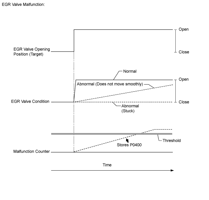
When the target and actual positions of the EGR valve are different, the ECM interprets this as a malfunction of the EGR valve and illuminates the MIL (1 trip detection logic).
EGR valve malfunction
-
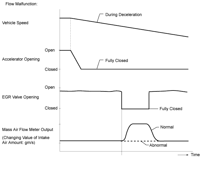
If the EGR valve is forcibly operated during deceleration but the intake air amount does not vary, the ECM determines that the EGR valve is malfunctioning. The ECM then illuminates the MIL (2 trip detection logic).
Flow malfunction
Tech Tips
-
If a large amount of carbon deposits exists in the EGR valve assembly, the following parts possibly also have deposits inside: The intake manifold and other parts related to the exhaust gas.
-
Read freeze frame data using the intelligent tester. Freeze frame data records the engine condition when malfunctions are detected. When troubleshooting, freeze frame data can help determine if the vehicle was moving or stationary, if the engine was warmed up or not, and other data from the time the malfunction occurred.
-
Be sure to carefully examine "Actual EGR Valve Pos.", "Target EGR Valve Pos." and "MAF" in the freeze frame data.
WIRING DIAGRAM
INSPECTION PROCEDURE
Note
-
After replacing the ECM, the new ECM needs registration Click here and initialization Click here.
-
When cleaning the EGR valve or diesel throttle body, use a piece of cloth soaked with cleaning solvent. Spraying the solvent directly onto these parts or soaking the parts in solvent may damage the parts.
PROCEDURE
-
CHECK ANY OTHER DTCS OUTPUT (IN ADDITION TO DTC P0400)
-
Connect the intelligent tester to the DLC3.
-
Turn the ignition switch to ON and turn the tester on.
-
Enter the following menus: Powertrain / Engine and ECT / DTC.
-
Read Current DTCs.
Result Result Proceed to P0400 A P0400 and other DTCs output B Tech Tips
-
DTC P0400 (flow malfunction) may be stored as a result of mass air flow meter malfunctions. If the mass air flow meter is malfunctioning, the vehicle will have poor acceleration and DTCs related to the mass air flow meter may be stored.
-
If the EGR valve circuit has an open or short circuit DTC P0405 or P0406 is stored.
-
B 
GO TO DTC CHART Click here
A 
-
-
CHECK FREEZE FRAME DATA (TARGET EGR POS. AND ACTUAL EGR VALVE POS.)
-
Connect the intelligent tester to the DLC3.
-
Turn the ignition switch to ON and turn the tester on.
-
Enter the following menus: Powertrain / Engine and ECT / DTC.
-
Read the values of Target EGR Position and Actual EGR Valve Pos. in Freeze Frame Data.
OK Actual EGR Valve Pos. is within +/- 1% of Target EGR Position.
OK 
CHECK FOR EXHAUST GAS LEAKS Click here
NG
INSPECT EGR VALVE ASSEMBLY Click here
-
-
CHECK FOR EXHAUST GAS LEAKS
-
Check for exhaust gas leaks.
Result Result Proceed to Exhaust gas leaks out from exhaust system A No leaks B
B
CHECK AIR INTAKE SYSTEM (AIR LEAKS AND BLOCKAGES) Click here
A
-
-
REPAIR EXHAUST GAS LEAK
-
Repair or replace the malfunctioning part in the exhaust system.
NEXT
-
-
CHECK AIR INTAKE SYSTEM (AIR LEAKS AND BLOCKAGES)
-
Check for air leaks and blockages in the air intake system.
Result Result Proceed to Leaks or blockages exist in the air intake system A No leaks and blockages in the intake system B Tech Tips
-
Check for abnormal disconnection, pipe and hose squashing, and any damage in the intake system.
-
Using your hand, check whether the pipes and hoses in the intake system are securely connected.
-
Air leaks from the intake system can be checked by applying soapy water and revving the engine.
-
Check for any modifications in the intake system made by the user.
-
B
INSPECT EGR VALVE ASSEMBLY Click here
A
-
-
REPAIR OR REPLACE AIR INTAKE SYSTEM
-
Repair or replace the malfunctioning part in the air intake system.
NEXT
-
-
INSPECT EGR VALVE ASSEMBLY
-
Remove the EGR valve assembly.
-
Visually check the electric EGR control valve for deposits.
If there are deposits, clean the electric EGR control valve.
Note
-
When cleaning the electric EGR control valve, make sure the valve is completely closed.
-
Do not forcibly open the valve, as it may be damaged or deformed.
-
When cleaning the electric EGR control valve, use a piece of cloth soaked with cleaning solvent. Spraying the solvent directly onto these parts or soaking the parts in the solvent may damage the parts.
-
-
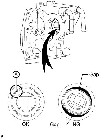
Hold the electric EGR control valve up to a light, and then from the side indicated by the arrow in the illustration, visually check that there is no gap between the valve and body.
OK No light passes through (there is no gap between the valve and body). If light passes through (there is a gap between the valve and body), replace the electric EGR control valve assembly.
Tech Tips
Light passes through part A shown in the illustration even if the valve is completely closed, this is not a problem.
OK
CHECK FOR DEPOSIT (EGR PASSAGE) Click here
NG
REPLACE EGR VALVE ASSEMBLY Click here
-
-
INSPECT EGR VALVE ASSEMBLY
-
Remove the EGR valve assembly.
-
Visually check the electric EGR control valve for deposits.
If there are deposits, clean the electric EGR control valve.
Note
-
When cleaning the electric EGR control valve, make sure the valve is completely closed.
-
Do not forcibly open the valve, as it may be damaged or deformed.
-
When cleaning the electric EGR control valve, use a piece of cloth soaked with cleaning solvent. Spraying the solvent directly onto these parts or soaking the parts in the solvent may damage the parts.
-
-
Hold the electric EGR control valve up to a light, and then from the side indicated by the arrow in the illustration, visually check that there is no gap between the valve and body.
OK No light passes through (there is no gap between the valve and body). If light passes through (there is a gap between the valve and body), replace the electric EGR control valve assembly.
Tech Tips
Light passes through part A shown in the illustration even if the valve is completely closed, this is not a problem.
OK
CHECK EGR VALVE ASSEMBLY Click here
NG
REPLACE EGR VALVE ASSEMBLY Click here
-
-
REPLACE EGR VALVE ASSEMBLY
-
Replace the EGR valve assembly Click here.
Note
Install the EGR valve assembly after checking the EGR valve assembly operation in the next step.
NEXT
-
-
CHECK EGR VALVE ASSEMBLY
-
With the EGR valve assembly removed from the vehicle, connect the EGR valve connector.
-
Connect the intelligent tester to the DLC3.
-
Turn the ignition switch to ON and turn the tester on.
-
Enter the following menus: Powertrain / Engine and ECT / Active Test / Control the EGR Step Position / Diesel EGR / Target EGR Pos. and Actual EGR Valve Pos..
-
Check that the EGR valve assembly operates.
OK Value smoothly changes to the set opening angle.
OK
CHECK FOR DEPOSIT (EGR PASSAGE) Click here
NG
CHECK HARNESS AND CONNECTOR (EGR VALVE - ECM) Click here
-
-
CHECK HARNESS AND CONNECTOR (EGR VALVE - ECM)
-
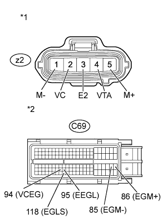
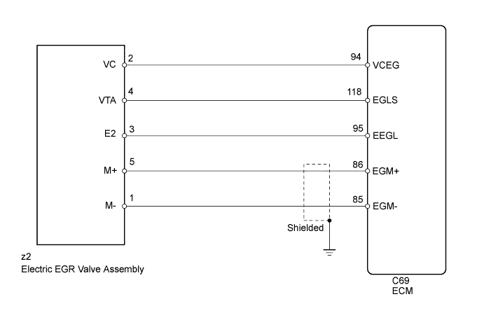
Text in Illustration *1 Front view of wire harness connector
(to Electric EGR Valve Assembly)
*2 Front view of wire harness connector
(to ECM)
Disconnect the EGR valve assembly connector.
-
Disconnect the ECM connector.
-
Measure the resistance according to the value(s) in the table below.
Standard Resistance (Check for Open) Tester Connection Condition Specified Condition z2-5 (M+) - C69-86 (EGM+) Always Below 1 Ω z2-1 (M-) - C69-85 (EGM-) Always Below 1 Ω z2-2 (VC) - C69-94 (VCEG) Always Below 1 Ω z2-4 (VTA) - C69-118 (EGLS) Always Below 1 Ω z2-3 (E2) - C69-95 (EEGL) Always Below 1 Ω Standard Resistance (Check for Short) Tester Connection Condition Specified Condition z2-5 (M+) or C69-86 (EGM+) - Body ground Always 10 kΩ or higher z2-2 (VC) or C69-94 (VCEG) - Body ground Always 10 kΩ or higher z2-4 (VTA) or C69-118 (EGLS) - Body ground Always 10 kΩ or higher -
Reconnect the EGR valve assembly connector.
-
Reconnect the ECM connector.
NG
REPAIR OR REPLACE HARNESS OR CONNECTOR Click here
OK
-
-
REPLACE EGR VALVE ASSEMBLY
Tech Tips
If the EGR valve assembly has already been replaced, proceed to the next step.
-
Replace the EGR valve assembly Click here.
NEXT
CHECK FOR DEPOSIT (EGR PASSAGE) Click here
-
-
REPAIR OR REPLACE HARNESS OR CONNECTOR
-
Repair or replace any malfunctioning harnesses or connectors.
NEXT
-
-
CHECK FOR DEPOSIT (EGR PASSAGE)
-
Check the deposit conditions in the EGR valve assembly.
Result Result Proceed to Wet carbon exists A Dry carbon exists B Tech Tips
-
Dry carbon: Carbon that is dried, not shiny, and peels easily.
-
Wet carbon: Tar carbon that is sticky, or shiny carbon that is hard and smooth to the touch.
-
If wet carbon deposits exist in the EGR valve and EGR passage, an EGR valve slow response malfunction may occur due to the sticky carbon deposit. In this case, hesitation or poor acceleration will occur while driving the vehicle.
-
B
REMOVE DEPOSIT (CLEAN EGR PASSAGE) Click here
A
-
-
REPLACE EGR VALVE ASSEMBLY
Tech Tips
If the EGR valve assembly has already been replaced, proceed to the next step.
-
Replace the EGR valve assembly Click here.
NEXT
CHECK FOR CAUSE OF FAILURE Click here
-
-
REMOVE DEPOSIT (CLEAN EGR PASSAGE)
-
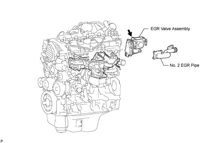
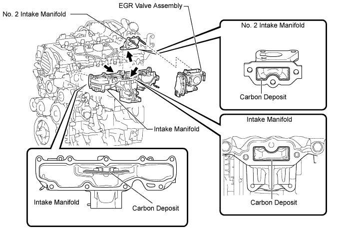
Remove the EGR valve assembly, No. 2 intake manifold and intake manifold.
-
Remove the deposits from those parts and clean the parts.
Note
-
When cleaning the EGR valve and diesel throttle body, use a piece of cloth soaked with cleaning solvent. Spraying the solvent directly onto these parts or soaking the parts in solvent may damage the parts.
-
Extreme care must be taken to prevent the removed deposits from falling into the engine unit during cleaning.
Tech Tips
Remove the intake manifold from the cylinder head when it has to be cleaned.
-
-
Reinstall the EGR valve assembly, No. 2 intake manifold and intake manifold.
NEXT
-
-
CHECK FOR CAUSE OF FAILURE
Tech Tips
If causes of black smoke emissions are in the engine, the exhaust system easily clogs with carbon deposits. Check for black smoke emissions in the exhaust gas, and repair the cause of black smoke, if it is necessary.
-
Start the engine and warm it up.
-
Turn the ignition switch off for 30 seconds or more.
-
Connect the intelligent tester to the DLC3.
-
Read the values of the Data List items when the engine is under the following conditions.
-
Ignition switch ON (engine not running).
-
Idling (after 1 minute or more elapsed).
Tech Tips
The shift lever should be in neutral and the A/C switch and all accessory switches should be off.
-
Engine maintained at 4500 rpm with no load.
-
-
Take snapshots with the intelligent tester for each engine condition above and analyze the cause of black smoke emission by referring to the table below.
Engine Condition Data List Item Standard Diagnostic Note Ignition switch ON MAP Difference between MAP and Atmosphere Pressure is +/-8 kPa If the difference exceeds the standard range, the sensor that indicates the value most different from the actual atmospheric pressure is malfunctioning. Atmosphere Pressure Injector Compensation Code*1 The injector compensation codes stored in the ECM match the injector compensation codes of the installed fuel injectors. If the codes do not match, input the correct codes by referring to "Registration". Idling Injection Feedback Val #1
Injection Feedback Val #2
Injection Feedback Val #3
Injection Feedback Val #4
-3.0 to 3.0 mm3/st
The injector for which the value is out of the standard range is malfunctioning. Injection Volume Less than 10 mm3/st
If the value of Injection Volume is 10 mm3/st or more and the values of all Injector Feedback Val. (#1 to #4) are within the standard range, replace the fuel injectors for all cylinders.
Coolant Temp
-
75°C (167°F) or more: After warming up the engine
-
When the engine is stopped and left overnight, the engine coolant temperature should be nearly equal to the intake air temperature.
If the value is out of the standard range, check the engine coolant temperature sensor circuit. 4500 rpm with no load MAP
Target Booster Pressure
Difference between MAP and Target Booster Pressure is +/-15 kPa or less - Corrected MAF Value*2 98 +/-20 g/sec.
When the following conditions are met:
-
Engine speed is 4500 rpm
-
MAP is 145 kPa
-
Intake Air Temp (Turbo) is 35°C
If the value is are out of the standard range, check the following items.
-
Intake system (leaks or blockages)
-
Turbocharger sub-assembly
-
Mass air flow meter circuit
-
Manifold absolute pressure sensor circuit
Tech Tips
-
*1: Check the Injector Compensation Codes by entering the following menus: Powertrain / Engine and ECT / Utility / Injector Compensation.
-
*2: The MAF value should be corrected by applying the following formula.
-
MAF corrected [g/sec] = MAF measured [g/sec] x {4500 x 142 x (35 + 273)}/ {Engine Speed [rpm] x MAP [kPa] x (Intake Air Temp (Turbo) + 273)}
-
Example data
-
Engine speed: 4520 rpm, MAP: 148 kPa, MAF: 104.3, Intake Air Temp (Turbo): 46°C
104.3 x {4500 x 142 x (35 + 273)} / {4520 x 148 x 46 + 273)} = 98.22
-
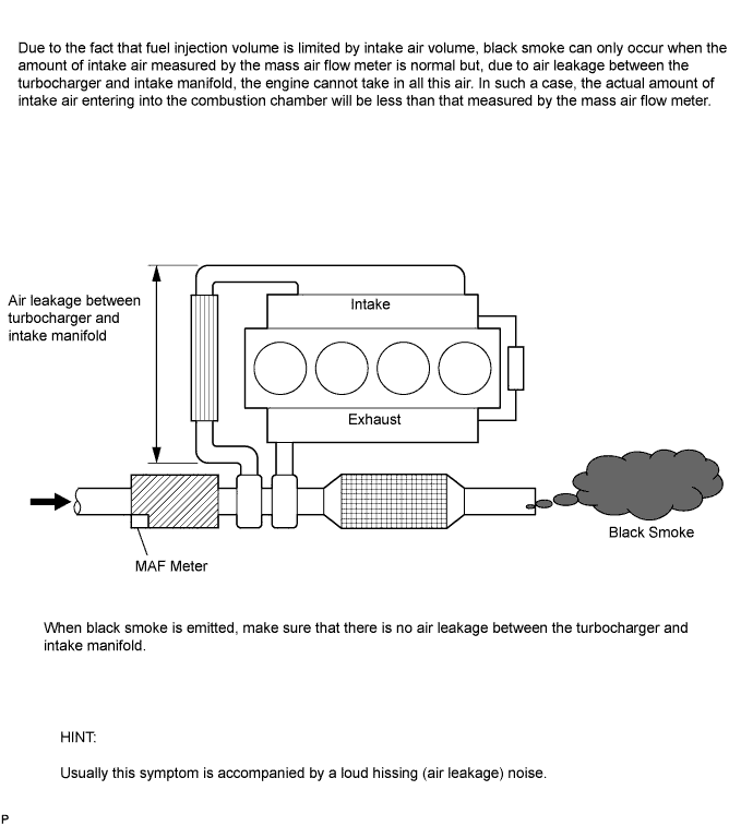
If the value calculated by applying the above formula is higher than the standard, leaks may exist between the turbocharger and intake manifold.
-
If the value calculated by applying the above formula is lower than the standard, leaks may exist between the air cleaner and turbocharger.
-
-
Check the vacuum hose connection (manifold absolute pressure sensor).
-
Check for air leaks in the intake pipes and hoses between the turbocharger and intake manifold.
-
Check for air leaks in the intake manifold.
-
Check for deposit in the EGR cooler.
-
Check the turbocharger sub-assembly.
NEXT
-
-
CHECK WHETHER DTC OUTPUT RECURS (DTC P0400)
-
Connect the intelligent tester to the DLC3.
-
Turn the ignition switch to ON and turn the tester on.
-
Clear DTCs Click here.
-
Turn the ignition switch off for 30 seconds or more.
-
Start the engine and warm it up.
-
Drive the vehicle with a stop-and-go city drive pattern for more than 10 minutes.
-
Decelerate from a speed of 80 km/h (50 mph) or more (fully closing the accelerator for approximately 5 seconds or more).
-
Enter the following menus: Powertrain / Engine and ECT / Utility / All Readiness.
-
Input DTC P0400.
-
Check the DTC judgment result.
Result Result Proceed to ABNORMAL A NORMAL B Tech Tips
If STATUS is INCOMPLETE or UNKNOWN, decelerate from a speed of 80 km/h (50 mph) or more (fully closing the accelerator for approximately 5 seconds or more) again.
B
END
A
-
-
REPLACE EGR VALVE ASSEMBLY
Tech Tips
If the EGR valve assembly has already been replaced, proceed to next step.
-
Replace the EGR valve assembly Click here.
NEXT
-
-
CHECK WHETHER DTC OUTPUT RECURS (DTC P0400)
-
Connect the intelligent tester to the DLC3.
-
Turn the ignition switch to ON and turn the tester on.
-
Clear DTCs Click here.
-
Turn the ignition switch off for 30 seconds or more.
-
Start the engine and warm it up.
-
Drive the vehicle with a stop-and-go city drive pattern for more than 10 minutes.
-
Decelerate from a speed of 80 km/h (50 mph) or more (fully closing the accelerator for approximately 5 seconds or more).
-
Enter the following menus: Powertrain / Engine and ECT / Utility / All Readiness.
-
Input DTC P0400.
-
Check the DTC judgment result.
Result Result Proceed to ABNORMAL A NORMAL B Tech Tips
If STATUS is INCOMPLETE or UNKNOWN, decelerate from a speed of 80 km/h (50 mph) or more (fully closing the accelerator for approximately 5 seconds or more) again.
B
END
A
-
-
REPLACE ECM
-
Replace the ECM Click here.
NEXT
-
-
CHECK WHETHER DTC OUTPUT RECURS (DTC P0400)
-
Turn the ignition switch to ON.
-
Turn the ignition switch off, and wait for 30 seconds or more.
-
Connect the intelligent tester to the DLC3.
-
Turn the ignition switch to ON and turn the tester on.
-
Clear DTCs Click here.
-
Start the engine and warm it up.
-
Drive the vehicle with a stop-and-go city drive pattern for more than 10 minutes.
-
Decelerate from a speed of 80 km/h (50 mph) or more (fully closing the accelerator for approximately 5 seconds or more).
-
Enter the following menus: Powertrain / Engine and ECT / DTC.
-
Confirm that the DTC is not output again.
Tech Tips
Perform the following procedure using the tester to determine whether or not the DTC judgment has been carried out.
-
Enter the following menus: Powertrain / Engine and ECT / Utility / All Readiness.
-
Input DTC P0400.
-
Check the DTC judgment result.
Tech Tips
If STATUS is INCOMPLETE or UNKNOWN, drive the vehicle with a stop-and-go city drive pattern for more than 10 minutes and decelerate from a speed of 80 km/h (50 mph) or more (fully closing the accelerator for approximately 5 seconds or more) again.
-
NEXT 
END
-