| DTC Code | DTC Name |
|---|---|
| P0335 | Crankshaft Position Sensor "A" Circuit |
| P0339 | Crankshaft Position Sensor "A" Circuit Intermittent |
DESCRIPTION
The crankshaft position sensor system consists of a crankshaft position sensor plate and pickup coil. The sensor plate has 34 teeth and is installed on the crankshaft. The pickup coil is made of an iron core and magnet. The sensor plate rotates, and a pulse signal is created as each tooth passes by the pickup coil. The pickup coil generates 34 signals for each revolution. Based on these signals, the ECM calculates the crankshaft position and engine speed. Using these calculations, the common rail injection system is controlled.
| DTC Detection Drive Pattern | DTC Detection Condition | Trouble Area |
|---|---|---|
| Crank or start engine | When the following condition is met (for 5 seconds during cranking or 0.5 seconds during engine start) (1 trip detection logic): No crankshaft position sensor signal is sent to the ECM while cranking. |
|
| DTC Detection Drive Pattern | DTC Detection Condition | Trouble Area |
|---|---|---|
| Engine running at 1000 rpm or more with vehicle stationary | No crankshaft position sensor signal is input to the ECM for 0.05 seconds or more, and conditions (a), (b) and (c) are met (1 trip detection logic):
|
|
| DTC No. | Data List |
|---|---|
| P0335 | Engine Speed |
| P0339 |
-
If DTC P0335 and/or P0339 is stored, the following symptoms may appear:
-
-
Difficult starting
-
Misfire
-
Combustion noise
-
Black smoke
-
White smoke
-
Lack of power
-
INSPECTION PROCEDURE
After replacing the ECM, the new ECM needs registration (Click here) and initialization (Click here).
-
Read freeze frame data using the intelligent tester. Freeze frame data records the engine condition when malfunctions are detected. When troubleshooting, freeze frame data can help determine if the vehicle was moving or stationary, if the engine was warmed up or not, and other data from the time the malfunction occurred.
-
The Data List item Engine Speed is calculated from the output of the crankshaft position sensor.
-
A DTC is also stored when the ground of a shielded wire is faulty.
PROCEDURE
- Click here
INSPECT CRANKSHAFT POSITION SENSOR
-
Disconnect the crankshaft position sensor connector.
-
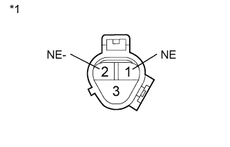
Measure the resistance according to the value(s) in the table below.
Standard Resistance Tester Connection Condition Specified Condition 1 (NE) - 2 (NE-) Cold 835 to 1400 Ω 1 (NE) - 2 (NE-) Hot 1060 to 1645 Ω Table 4. Text in Illustration *1 Component without harness connected
(Crankshaft Position Sensor)
Tip:In the table above, the terms "Cold" and "Hot" refer to the temperature of the coils in the sensor. "Cold" means approximately -10 to 50°C (14 to 122°F). "Hot" means approximately 50 to 100°C (122 to 212°F).
-
Reconnect the crankshaft position sensor connector.
- OKClick here
- NGClick here
-
- Click here
CHECK HARNESS AND CONNECTOR (CRANKSHAFT POSITION SENSOR - ECM)
-
Disconnect the crankshaft position sensor connector.
-
Disconnect the ECM connector.
-
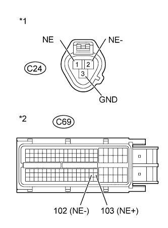
Measure the resistance according to the value(s) in the table below.
Standard Resistance (Check for Open) Tester Connection Condition Specified Condition C24-1 (NE) - C69-103 (NE+) Always Below 1 Ω C24-2 (NE-) - C69-102 (NE-) Always Below 1 Ω C24-3 (GND) - Body ground Always Below 1 Ω Standard Resistance (Check for Short) Tester Connection Condition Specified Condition C24-1 (NE) or C69-103 (NE+) - Body ground Always 10 kΩ or higher C24-2 (NE-) or C69-102 (NE-) - Body ground Always 10 kΩ or higher Table 5. Text in Illustration *1 Front view of wire harness connector
(to Crankshaft Position Sensor)
*2 Front view of wire harness connector
(to ECM)
-
Reconnect the crankshaft position sensor connector.
-
Reconnect the ECM connector.
- OKClick here
- NGClick here
-
- Click here
CHECK CRANKSHAFT POSITION SENSOR (SENSOR INSTALLATION)
-
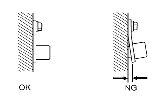
Check the sensor installation.
OK Sensor is installed correctly.
- OKClick here
- NGClick here
-
- Click here
CHECK NO. 1 CRANKSHAFT POSITION SENSOR PLATE
-
Check the teeth of the sensor plate.
OK The sensor plate teeth do not have any cracks or deformation.
- OKClick here
- NGClick here
-
- Click here
REPLACE ECM
-
Replace the ECM (Click here).
- NEXTClick here
-
- Click here
REPLACE CRANKSHAFT POSITION SENSOR
-
Replace the crankshaft position sensor (Click here).
- NEXTClick here
-
- Click here
REPAIR OR REPLACE HARNESS OR CONNECTOR
-
Repair or replace the harness or connector.
- NEXTClick here
-
- Click here
SECURELY REINSTALL SENSOR
-
Securely reinstall the sensor (Click here).
- NEXTClick here
-
- Click here
REPLACE NO. 1 CRANKSHAFT POSITION SENSOR PLATE
-
Replace the No. 1 crankshaft position sensor plate (Click here).
- NEXTClick here
-
- Click here
CONFIRM WHETHER MALFUNCTION HAS BEEN SUCCESSFULLY REPAIRED
-
Connect the intelligent tester to the DLC3.
-
Clear the DTCs (Click here).
-
Turn the ignition switch off for 30 seconds or more.
-
Start the engine and run it at 1000 rpm or more for 5 seconds or more.
-
Confirm that the DTC is not output again.
- NEXTClick here
-
- Click here
END