SFI SYSTEM, Diagnostic DTC:P0660

| DTC Code | DTC Name |
|---|---|
| P0660 | Intake Manifold Tuning Valve Control Circuit / Open (Bank 1) |
DESCRIPTION
This circuit opens and closes the Intake Air Control Valve (IACV) in response to changes in the engine load in order to increase the intake efficiency (ACIS: Acoustic Control Induction System).
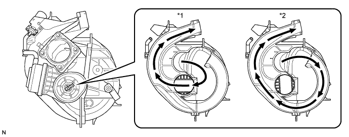
| *1 | Intake Air Control Valve Open | *2 | Intake Air Control Valve Close |
| DTC No. | DTC Detection Condition | Trouble Area |
|---|---|---|
| P0660 | The following conditions are met simultaneously for 0.5 seconds or more (2 trip detection logic):
|
|
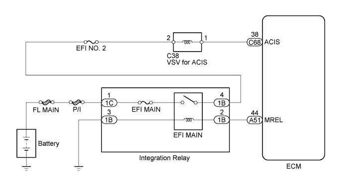
WIRING DIAGRAM
INSPECTION PROCEDURE
Note
Inspect the fuses for circuits related to this system before performing the following inspection procedure.
PROCEDURE
-
PERFORM ACTIVE TEST USING INTELLIGENT TESTER (OPERATE VSV FOR ACIS)
-
Connect the intelligent tester to the DLC3.
-
Start the engine and turn the tester on.
-
Enter the following menus: Powertrain / Engine and ECT / Active Test / Active the VSV for Intake Control.
-
Check if operating noise can be heard when operating the air intake control valve using the intelligent tester.
OK Operating noise can be heard.
NG 
INSPECT VSV FOR ACIS Click here
OK 
CHECK FOR INTERMITTENT PROBLEMS Click here
-
-
INSPECT VSV FOR ACIS
-
Check the VSV for ACIS Click here.
NG 
REPLACE VSV FOR ACIS Click here
OK 
-
-
CHECK VSV FOR ACIS (POWER SOURCE)
-
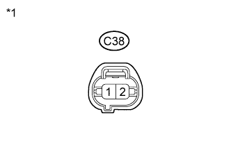
Text in Illustration *1 Front view of wire harness connector
(to VSV for ACIS)
Disconnect the VSV for ACIS connector.
-
Turn the ignition switch to ON.
-
Measure the voltage according to the value(s) in the table below.
Standard Voltage Tester Connection Switch Condition Specified Condition 1 - 2 Ignition switch ON 11 to 14 V
NG
CHECK HARNESS AND CONNECTOR (VSV FOR ACIS - INTEGRATION RELAY) Click here
OK
-
-
CHECK HARNESS AND CONNECTOR (VSV FOR ACIS - ECM)
-
Disconnect the VSV for ACIS connector.
-
Disconnect the ECM connector.
-
Measure the resistance according to the value(s) in the table below.
Standard Resistance (Check for open) Tester Connection Condition Specified Condition C38-1 - C68-38 (ACIS) Always Below 1 Ω Standard Resistance (Check for short) Tester Connection Condition Specified Condition C38-1 or C68-38 (ACIS) - Body ground Always 10 kΩ or higher -
Reconnect the ECM connector.
-
Reconnect the VSV for ACIS connector.
NG
REPAIR OR REPLACE HARNESS OR CONNECTOR (VSV FOR ACIS - ECM)
OK
REPLACE ECM Click here
-
-
CHECK HARNESS AND CONNECTOR (VSV FOR ACIS - INTEGRATION RELAY)
-
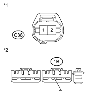
Text in Illustration *1 Front view of wire harness connector
(to VSV for ACIS)
*2 Front view of wire harness connector
(to Integration Relay)
Disconnect the VSV for ACIS connector.
-
Remove the integration relay (EFI MAIN relay) from the engine room No. 1 relay block and disconnect the integration relay connector.
-
Measure the resistance according to the value(s) in the table below.
Standard Resistance (Check for open) Tester Connection Condition Specified Condition C38-2 - 1B-4 Always Below 1 Ω Standard Resistance (Check for short) Tester Connection Condition Specified Condition C38-2 or 1B-4 - Body ground Always 10 kΩ or higher -
Reconnect the integration relay connector.
-
Reinstall the integration relay.
-
Reconnect the VSV for ACIS connector.
NG
REPAIR OR REPLACE HARNESS OR CONNECTOR (VSV FOR ACIS - INTEGRATION RELAY)
OK
GO TO ECM POWER SOURCE CIRCUIT Click here
-