CONTINUOUSLY VARIABLE VALVE LIFT CONTROLLER REMOVAL

-
REMOVE BATTERY SERVICE HOLE COVER
-
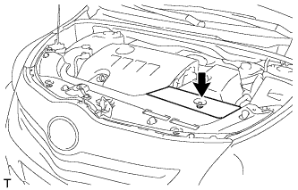
Remove the clip and battery service hole cover.
-
-
REMOVE RADIATOR SUPPORT OPENING COVER
-
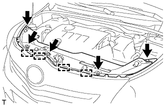
Remove the 5 clips.
-
Detach the 4 hooks and remove the radiator support opening cover.
-
-
PRECAUTION
Note
After turning the ignition switch off, waiting time may be required before disconnecting the cable from the battery terminal. Therefore, make sure to read the disconnecting the cable from the battery terminal notice before proceeding with work Click here.
-
DISCONNECT CABLE FROM NEGATIVE BATTERY TERMINAL
Note
When disconnecting the cable, some systems need to be initialized after the cable is reconnected Click here.
-
REMOVE NO. 2 CYLINDER HEAD COVER
-
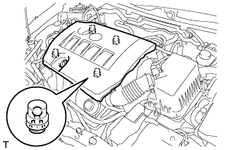
Hold the rear of the cover and raise it to detach the 2 clips on the rear of the cover. Continue to raise the cover to detach the 2 clips on the front of the cover and remove the cover.
Note
Attempting to detach both front and rear clips at the same time may cause the cover to break.
-
-
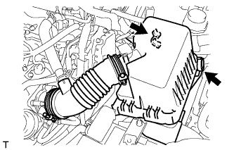
REMOVE AIR CLEANER CAP SUB-ASSEMBLY
-
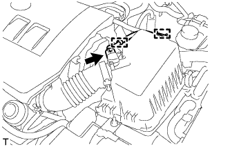
Disconnect the mass air flow meter connector.
-
Detach the 2 clamps and disconnect the wire harness.
-
Disconnect the 2 clamps.
-
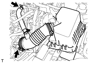
Disconnect the PCV hose.
-
Loosen the band and remove the air cleaner cap.
-
-
REMOVE AIR CLEANER CASE SUB-ASSEMBLY
-
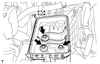
Detach the wire harness clamp from the air cleaner case.
-
Remove the 3 bolts and air cleaner case.
-
-
REMOVE BATTERY CLAMP SUB-ASSEMBLY
-
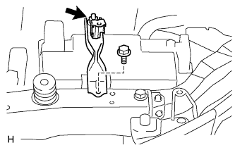
Disconnect the cable from the positive (+) battery terminal.
-
Remove the bolt and loosen the nut.
-
Remove the battery clamp.
-
-
REMOVE BATTERY
-
REMOVE BATTERY TRAY
-
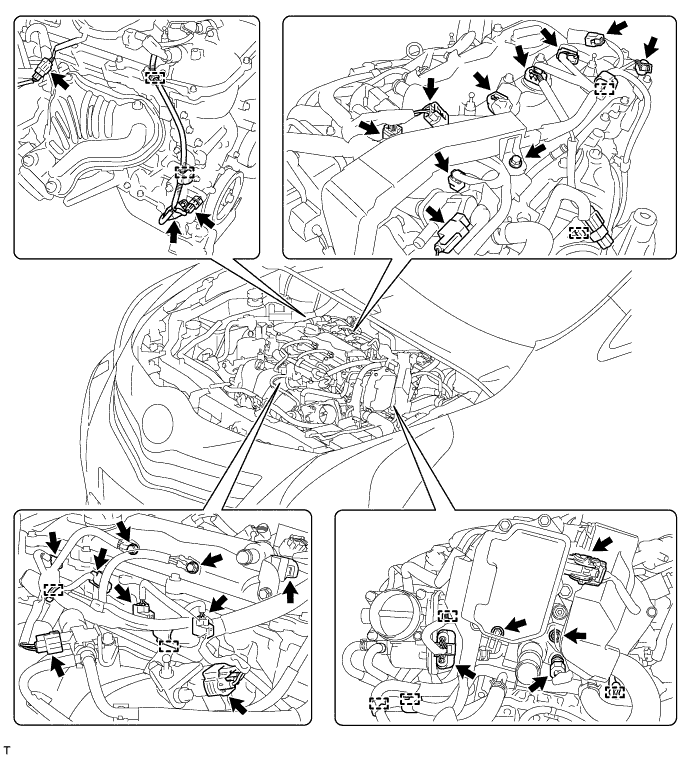
DISCONNECT ENGINE WIRE
-
Detach the 10 clamps, and then disconnect the connectors.
-
Remove the 3 bolts and 2 nuts, and then disconnect the engine wire.
-
-
REMOVE IGNITION COIL ASSEMBLY
-
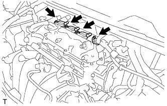
Remove the 4 bolts and 4 ignition coils.
-
-
REMOVE AIR TUBE
-
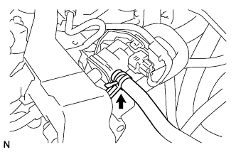
Disconnect the fuel vapor feed hose from the purge VSV.
-
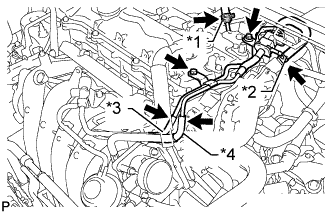
Text in Illustration *1 Union To Connector Tube Hose *2 Vacuum Hose *3 No. 2 Air Hose *4 No. 1 Fuel Vapor Feed Hose Disconnect the union to connector tube hose and vacuum hose.
-
Disconnect the No. 2 air hose and No. 1 fuel vapor feed hose.
-
Remove the 2 bolts and air tube.
-
-
REMOVE CYLINDER HEAD COVER SUB-ASSEMBLY
-
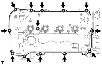
Remove the 13 bolts, seal washer and cylinder head cover.
-
Remove the 3 gaskets from the camshaft bearing cap.
Note
As gaskets may stick to the cylinder head cover, be careful not to drop any of the gaskets into the engine when removing the cylinder head cover.
-
-
REMOVE CYLINDER HEAD COVER GASKET
-
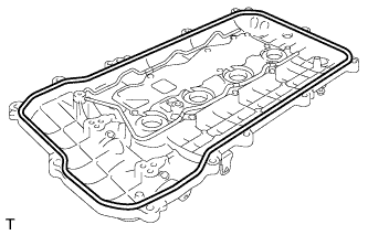
Remove the cylinder head cover gasket.
-
-
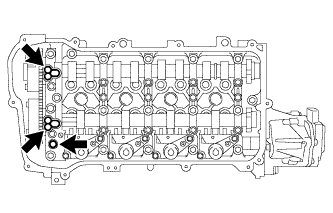
REMOVE CONTINUOUSLY VARIABLE VALVE LIFT CONTROLLER ASSEMBLY
-
Using a screwdriver, slide the valve lift control actuator connector clip from the valve lift control actuator connector.
Note
Slide only the upper part of the valve lift control actuator connector clip, as the straight pin falls out from the bottom if the valve lift control actuator connector clip is completely removed.
-
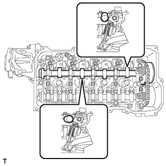
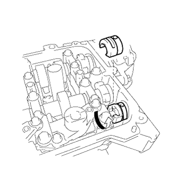
Rotate the crankshaft clockwise until the intake camshaft position at the No. 1 cylinder and No. 3 cylinder is as shown in the illustration.
Tech Tips
If the camshaft position is not as shown in the illustration, rotate the crankshaft clockwise again so that the camshaft is aligned as shown in the illustration.
-
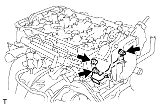
Remove the bolt, 2 nuts and wire harness clamp bracket.
-
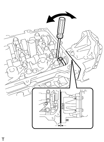
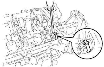
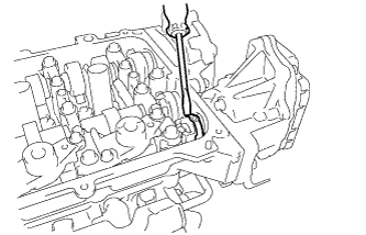
Using a screwdriver, lightly pry the valve lift control actuator connector to make a space between the continuously variable valve lift controller and camshaft housing.
Note
-
Do not forcefully pry the valve lift control actuator connector.
-
Do not damage the camshaft housing or camshaft bearing cap.
-
-
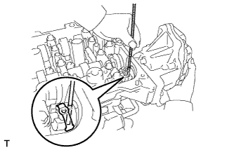
Using a magnet hand, remove the straight pin from the valve lift control actuator connector.
Tech Tips
The pin can be removed by utilizing the space between the continuously variable valve lift controller and camshaft housing to move the continuously variable valve lift controller so that there is no load on the pin.
Note
Do not drop the straight pin into the engine.
-
Using a screwdriver, remove the valve lift control actuator connector clip from the valve lift control actuator connector.
Note
Do not drop the valve lift control actuator connector clip into the engine.
-
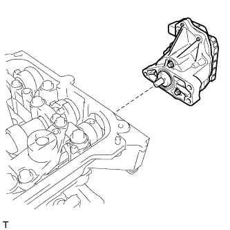
Remove the continuously variable valve lift controller from the camshaft housing.
-
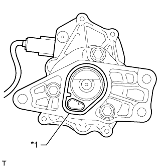
Text in Illustration *1 O-Ring Remove the O-ring from the continuously variable valve lift controller.
-
Remove the valve lift control actuator connector from the valve rocker shaft.
Tech Tips
There are two types of valve lift control actuator connectors. One type is removed by rotating the connector, and the other type can be removed without being rotated.
-