ECM INSTALLATION

-
INSTALL ECM
-
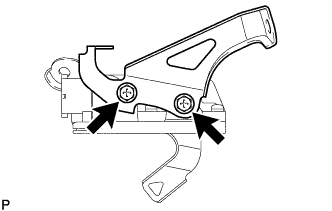
Install the No. 2 ECM bracket to the ECM with the 2 screws.
- Torque:
- 3.0 N*m { 31 kgf*cm, 27 in.*lbf }
-
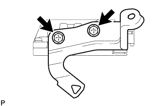
Install the No. 1 ECM bracket to the ECM with the 2 screws.
- Torque:
- 3.0 N*m { 31 kgf*cm, 27 in.*lbf }
-
Install the ECM with the 2 bolts.
- Torque:
- 8.0 N*m { 82 kgf*cm, 71 in.*lbf }
-
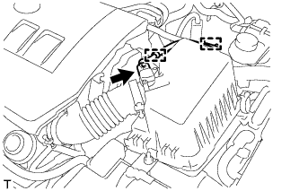
Connect the 2 ECM connectors and lock with the 2 levers.
Note
-
When connecting the connectors, make sure that dirt, water or other foreign matter does not get caught between the connectors and other parts.
-
Make sure that the 2 levers are securely lowered.
-
-
Attach the wire harness clamp.
-
-
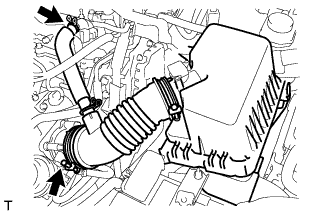
CONNECT NO. 2 AIR CLEANER INLET
-
Connect the No. 2 air cleaner inlet to the vehicle body with the bolt.
- Torque:
- 7.0 N*m { 71 kgf*cm, 62 in.*lbf }
-
-
INSTALL NO. 1 AIR CLEANER INLET
-
Attach the 2 claws to install the No. 1 air cleaner inlet.
-
Install the clip.
-
-
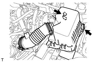
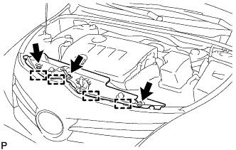
INSTALL AIR CLEANER CASE SUB-ASSEMBLY
-
Install the air cleaner case with the 3 bolts.
- Torque:
- 7.0 N*m { 71 kgf*cm, 62 in.*lbf }
-
Attach the wire harness clamp to the air cleaner case.
-
-
INSTALL AIR CLEANER FILTER ELEMENT SUB-ASSEMBLY
-
INSTALL AIR CLEANER CAP SUB-ASSEMBLY
-
Connect the air cleaner cap with the band.
-
Connect the PCV hose.
-
Connect the 2 clamps.
-
Attach the 2 clamps and connect the wire harness.
-
Connect the mass air flow meter connector.
-
-
INSTALL NO. 2 CYLINDER HEAD COVER
-
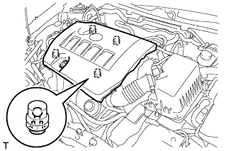
Attach the 4 clips to install the cover.
Note
-
Be sure to attach the clips securely.
-
Do not apply excessive force or hit the cover to attach the clips. This may cause the cover to break.
-
-
-
CONNECT CABLE TO NEGATIVE BATTERY TERMINAL
Note
When disconnecting the cable, some systems need to be initialized after the cable is reconnected Click here.
-
INSTALL RADIATOR SUPPORT OPENING COVER
-
Attach the 4 hooks to install the radiator support opening cover.
-
Install the 3 clips.
-
-
PERFORM INITIALIZATION
Note
Perform the following procedure after replacing the throttle body assembly or any throttle body assembly components. The following procedure should also be performed if the throttle body assembly is cleaned.
-
Turn the ignition switch to ON without operating the accelerator pedal.
Note
If the accelerator pedal is operated, perform the above steps again.
-
Connect the intelligent tester to the DLC3 and clear the DTCs Click here.
-
Start the engine and check that the MIL is not illuminated and that the idle speed is within the specified range when the A/C is switched off after the engine is warmed up.
Standard Idle Speed Item Specified Condition for Manual Transaxle 580 to 680 rpm for CVT 600 to 700 rpm Note
-
Be sure to perform this step with all accessories off.
-
Make sure that the shift lever is in N (neutral) or P.
-
-
Enter the following menus: Powertrain / Engine and ECT / Data List / All Data / Throttle Sensor Position. Fully depress the accelerator pedal and check that the value is 60% or more.
-
Perform a road test and confirm that there are no abnormalities.
-
-
RESET MEMORY (for CVT)
-
When replacing the ECM, perform the Reset Memory procedure (initialization) Click here.
-