FRONT BUMPER (for Sport Package) REASSEMBLY

-
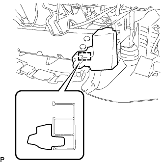
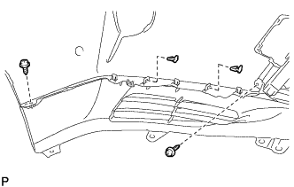
INSTALL FRONT BUMPER SIDE RETAINER LH
-
Engage the 2 claws to install the front bumper side retainer LH.
-
Install the bolt.
- Torque:
- 5.4 N*m { 55 kgf*cm, 48 in.*lbf }
-
Engage the clip as shown in the illustration.
-
-
INSTALL FRONT BUMPER SIDE RETAINER RH
Tech Tips
Use the same procedure as for the LH side.
-
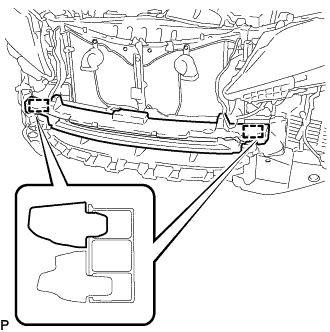
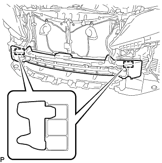
INSTALL FRONT BUMPER REINFORCEMENT
-
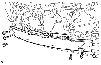
Install the front bumper reinforcement with the 6 bolts.
- Torque:
- 35 N*m { 357 kgf*cm, 26 ft.*lbf }
-
Engage the 3 clamps.
-
-
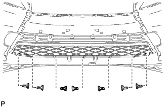
INSTALL LOWER AIR DUCT
-
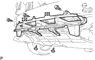
Disengage the 2 guides.
-
Install the lower air duct with the 2 bolts and 3 clips.
- Torque:
- 7.5 N*m { 77 kgf*cm, 66 in.*lbf }
-
-
INSTALL FRONT BUMPER ENERGY ABSORBER LH (for Separate Type)
-
Engage the guide to install the front bumper energy absorber LH.
-
-
INSTALL FRONT BUMPER ENERGY ABSORBER RH (for Separate Type)
Tech Tips
Use the same procedure as for the LH side.
-
INSTALL FRONT BUMPER ENERGY ABSORBER (for Separate Type)
-
Engage the 2 guides to install the front bumper energy absorber.
-
-
INSTALL FRONT BUMPER ENERGY ABSORBER (except Separate Type)
-
Engage the 2 guides to install the front bumper energy absorber.
-
-
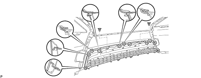
INSTALL LOWER NO. 1 RADIATOR GRILLE (w/ Front Fender Name Plate)
-
Engage the 11 claws to install the lower No. 1 radiator grille.
-
Install the 2 front bumper side retainers.
-
-
INSTALL LOWER NO. 1 RADIATOR GRILLE (w/o Front Fender Name Plate)
-
Engage the 11 claws to install the lower No. 1 radiator grille.
-
Install the 2 front bumper side retainers.
-
-
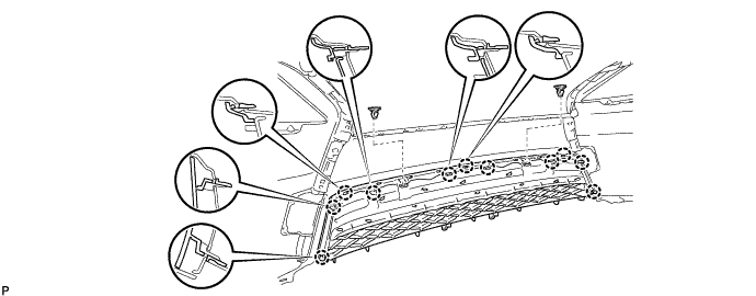
INSTALL FRONT BUMPER GUARD
-
Engage the 10 claws to install the front bumper guard.
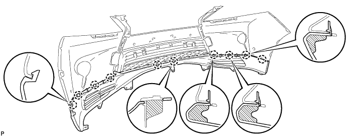
-
Install the 7 front bumper side retainers.
-
Install the 2 screws and 2 front bumper side retainers.
Tech Tips
Use the same procedure for the RH side and LH side.
-
-
INSTALL FOG LIGHT COVER LH
-
Engage the 3 claws to install the fog light cover LH to the fog light mounting bracket LH.
-
Engage the 3 claws to install the fog light cover LH with the fog light mounting bracket LH.
-
Install the 2 screws.
-
-
INSTALL FOG LIGHT COVER RH
Tech Tips
Use the same procedure as for the LH side.
-
INSTALL RADIATOR GRILLE ASSEMBLY
-
Engage the 10 claws.
-
Install the radiator grille assembly with the 6 screws.
-
w/ LEXUS Parking Assist-sensor System:
-
Engage the 2 clamps to connect the sensor wire.
-
-
w/ Headlight Cleaner System:
-
Engage the 2 clamps to connect the headlight cleaner hose.
-
-
-
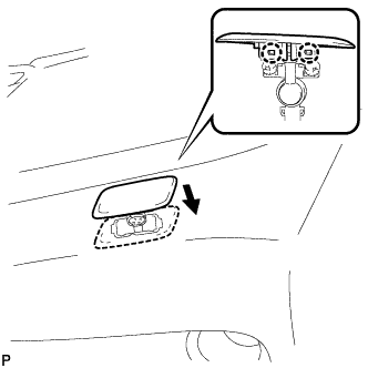
INSTALL FRONT BUMPER HOLE COVER LH
-
Engage the 2 claws to install the front bumper hole cover LH to the center radiator grille moulding LH.
-
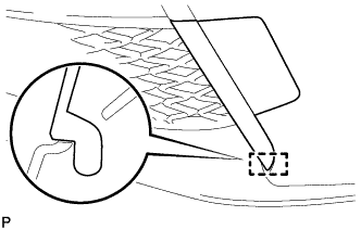
Engage the guide.
-
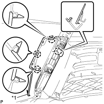
Text in Illustration *1 Hook Engage the hook.
-
Engage the 4 claws to install the front bumper hole cover LH with the center radiator grille moulding LH.
-
-
INSTALL FRONT BUMPER HOLE COVER RH
Tech Tips
Use the same procedure as for the LH side.
-
INSTALL FRONT FENDER LINER RETAINER
-
Engage the claws to install the 2 front fender liner retainers.
Tech Tips
Use the same procedure for the RH side and LH side.
-
-
INSTALL FRONT BUMPER EXTENSION MOUNTING BRACKET (for Short Type)
-
Disengage the 2 claws.
-
Install the front bumper extension mounting bracket with the 2 screws.
- Torque:
- 7.5 N*m { 77 kgf*cm, 66 in.*lbf }
-
-
INSTALL FRONT BUMPER EXTENSION MOUNTING BRACKET (for Long Type)
-

Disengage the 2 claws.
-
Install the front bumper extension mounting bracket with the 2 screws.
- Torque:
- 7.5 N*m { 77 kgf*cm, 66 in.*lbf }
-
-
INSTALL FOG LIGHT ASSEMBLY LH
-
Engage the 2 guides to temporarily install the fog light assembly.
-
Install the fog light assembly with the screw.
-
-
INSTALL FOG LIGHT ASSEMBLY RH
Tech Tips
Use the same procedure as for the LH side.
-
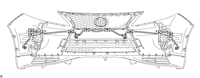
INSTALL SENSOR WIRE (w/ LEXUS Parking Assist-sensor System)
-
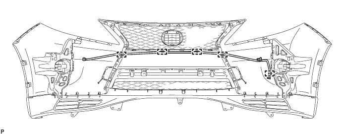
Engage the 9 clamps to install the sensor wire.
-
-
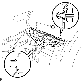
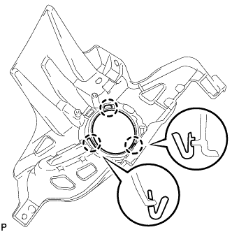
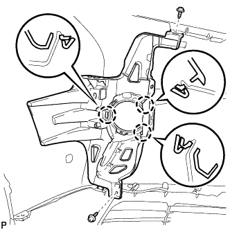
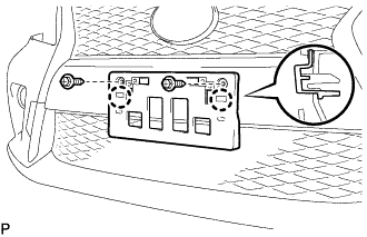
INSTALL NO. 1 ULTRASONIC SENSOR RETAINER (w/ LEXUS Parking Assist-sensor System)
-
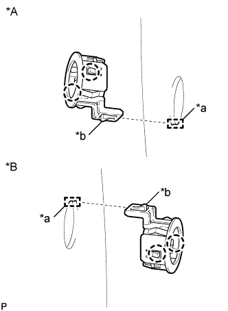
Text in Illustration *A RH Side *B LH Side *a Keyhole *b Snap Engage the 2 claws to install the No. 1 ultrasonic sensor retainer to the front bumper assembly.
Note
-
Do not damage the front bumper with the protrusion when installing the retainer.
-
Securely install the No. 1 ultrasonic sensor retainer so that there are no gaps between the retainer and surface of the front bumper.
Tech Tips
When installing the retainer, align the keyhole and snap as shown in the illustration.
-
-
-
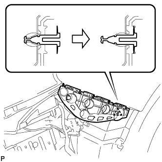
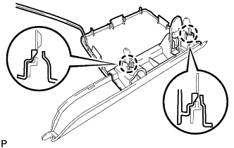
INSTALL NO. 1 ULTRASONIC SENSOR (w/ LEXUS Parking Assist-sensor System)
-
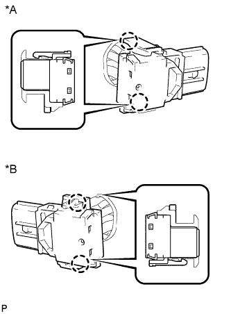
Text in Illustration *A RH Side *B LH Side Engage the 2 claws to install the No. 1 ultrasonic sensor to the No. 1 ultrasonic sensor retainer.
Note
Push the No. 1 ultrasonic sensor retainer from the outside of the bumper when there is a gap between the retainer and the bumper surface. In this case, do not push on the ultrasonic sensor.
-
for Front Sensor:
-
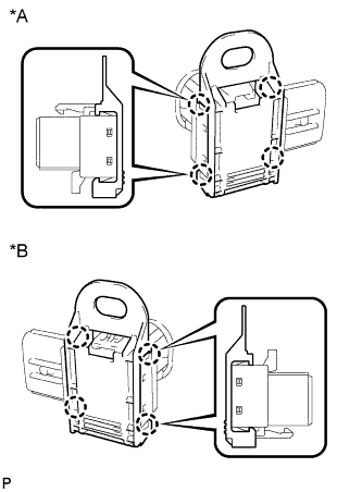
Text in Illustration *A RH Side *B LH Side Engage the 4 claws to install the ultrasonic sensor clip.
-
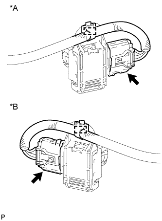
Text in Illustration *A RH Side *B LH Side Engage the clamp.
-
Connect the connector.
-
-
for Corner Sensor:
-
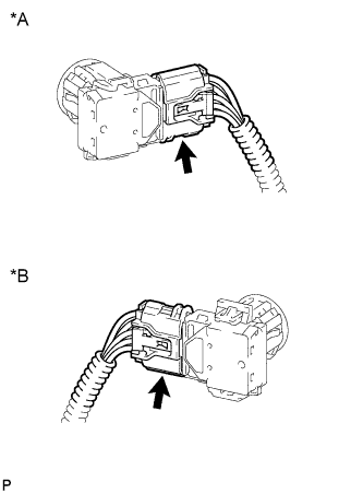
Text in Illustration *A RH Side *B LH Side Connect the connector.
-
-
-
INSTALL HEADLIGHT CLEANER HOSE (w/ Headlight Cleaner System)
-
Engage the 5 clamps to install the headlight cleaner hose.
-
-
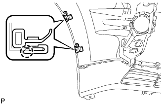
INSTALL HEADLIGHT WASHER ACTUATOR SUB-ASSEMBLY LH (w/ Headlight Cleaner System)
-
Engage the guide.

-
While pushing the tab shown by arrow (a), engage the claw as shown in the illustration.
-
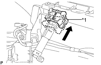
Text in Illustration *1 Headlight Cleaner Actuator Clamp Push up the headlight cleaner actuator clamp.
-
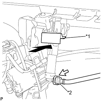
Text in Illustration *1 Headlight Cleaner Clamp *2 Headlight Cleaner Hose Install the headlight cleaner clamp.
-
Connect the headlight cleaner hose.
-
-
INSTALL HEADLIGHT WASHER ACTUATOR SUB-ASSEMBLY RH (w/ Headlight Cleaner System)
Tech Tips
Use the same procedure as for the LH side.
-
INSTALL HEADLIGHT WASHER NOZZLE SUB-ASSEMBLY LH (w/ Headlight Cleaner System)
-
Engage the 2 claws to install the headlight washer nozzle sub-assembly LH.
-
-
INSTALL HEADLIGHT WASHER NOZZLE SUB-ASSEMBLY RH (w/ Headlight Cleaner System)
Tech Tips
Use the same procedure as for the LH side.