STOP LIGHT CONTROL RELAY INSTALLATION

-
INSTALL STOP LIGHT CONTROL RELAY ASSEMBLY
-
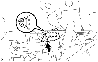
Connect the connector.
-
Engage the clamp to install the stop light control relay assembly.
-
-
INSTALL INSTRUMENT PANEL JUNCTION BLOCK ASSEMBLY (for LHD)
-
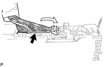
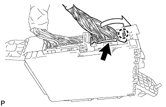
Engage the claw to connect the connector as shown in the illustration.
-
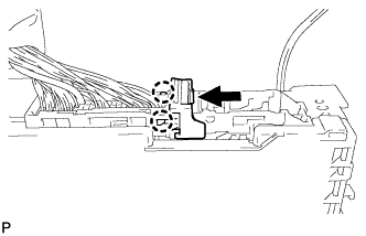
Engage the 2 claws to lock the connector lock as shown in the illustration.
-
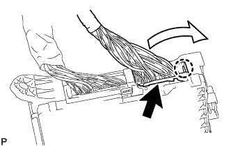
Engage the claw to connect the connector as shown in the illustration.
-
Install the instrument panel junction block assembly with the 2 nuts.
- Torque:
- 8.0 N*m { 82 kgf*cm, 71 in.*lbf }
-
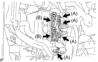
Connect the 4 connectors (A).
-
Engage the 2 claws to connect the 2 connectors (B).
-
Connect the 4 connectors.
-
-
INSTALL INSTRUMENT PANEL JUNCTION BLOCK ASSEMBLY (for RHD)
-
Engage the claw to connect the connector as shown in the illustration.
-
Engage the 2 claws to lock the connector lock as shown in the illustration.
-
Engage the claw to connect the connector as shown in the illustration.
-
Install the instrument panel junction block assembly with the bolt and nut.
- Torque:
- Bolt
- 13 N*m { 127 kgf*cm, 9 ft.*lbf }
- Nut
- 8.0 N*m { 82 kgf*cm, 71 in.*lbf }
-
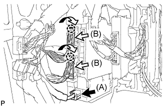
Connect the connector (A).
-
Engage the 2 claws to connect the 2 connectors (B) as shown in the illustration.
-
Connect the 3 connectors.
-
-
INSTALL GLOVE COMPARTMENT DOOR ASSEMBLY (for RHD)
-
Connect each connector.
-
Engage the claw, 4 clips and guide.
-
Install the glove compartment door assembly with the 5 screws <F>.
-
-
INSTALL DRIVER SIDE KNEE AIRBAG ASSEMBLY (for LHD)
-
INSTALL FRONT PASSENGER SIDE KNEE AIRBAG ASSEMBLY (for RHD)