LIGHTING SYSTEM, Diagnostic DTC:B2430, B2431

| DTC Code | DTC Name |
|---|---|
| B2430 | LED Headlight LH Circuit Malfunction |
| B2431 | LED Headlight RH Circuit Malfunction |
DESCRIPTION
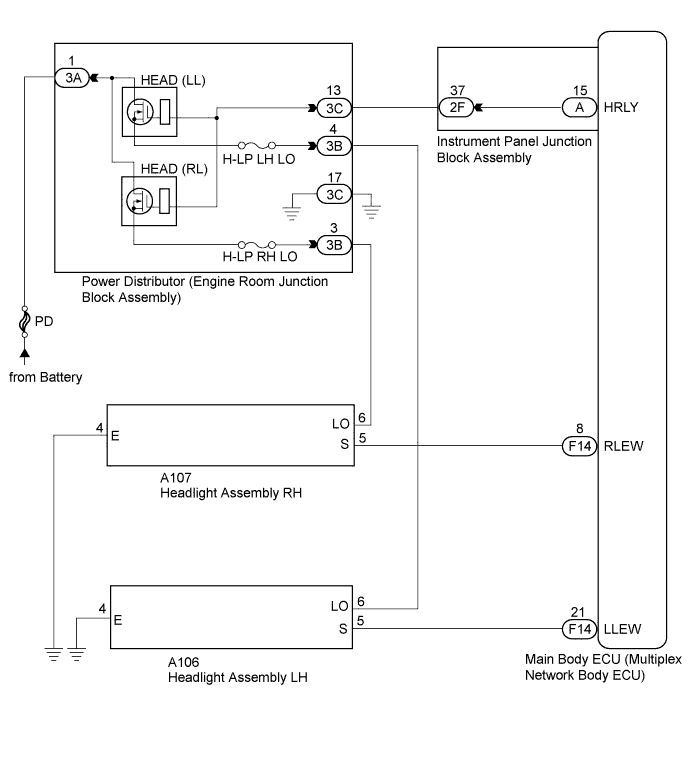
These DTCs are stored when the low beam headlights do not illuminate, or a malfunction is detected in the communication between the headlight assembly and the main body ECU (multiplex network body ECU).
| DTC Code | DTC Detection Condition | Trouble Area |
|---|---|---|
| B2430 | LED headlight LH circuit malfunction |
|
| B2431 | LED headlight RH circuit malfunction |
|
WIRING DIAGRAM
INSPECTION PROCEDURE
Note
Inspect the fuses for circuits related to this system before performing the following inspection procedure.
PROCEDURE
-
CHECK FOR DTC
-
Clear the DTCs Click here.
-
Check for DTCs Click here.
Result Result Proceed to Both DTC B2430 and DTC B2431 are not output. A Both DTC B2430 and DTC B2431 are output. B DTC B2430 or B2431 is output. C
B 
INSPECT POWER DISTRIBUTOR (ENGINE ROOM JUNCTION BLOCK ASSEMBLY) Click here
C
INSPECT HEADLIGHT ASSEMBLY Click here
A 
USE SIMULATION METHOD TO CHECK Click here
-
-
INSPECT POWER DISTRIBUTOR (ENGINE ROOM JUNCTION BLOCK ASSEMBLY)
-
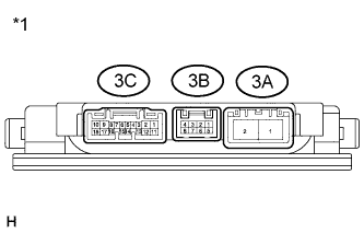
Text in Illustration *1 Component without harness connected
(Power Distributor (Engine Room Junction Block Assembly))
Remove the power distributor (engine room junction block assembly) from the engine room relay block Click here.
-
Connect a positive (+) lead from the battery to terminal 3A-1
-
Connect a negative (-) lead from the battery to terminals 3C-13 and 3C-17.
-
Measure the voltage according to the value(s) in the table below.
Standard Voltage Tester Connection Condition Specified Condition 3B-3 - Battery negative Always 11 to 14 V 3B-4 - Battery negative Always 11 to 14 V
NG 
REPLACE POWER DISTRIBUTOR (ENGINE ROOM JUNCTION BLOCK ASSEMBLY) Click here
OK 
-
-
CHECK HARNESS AND CONNECTOR (POWER DISTRIBUTOR - BATTERY AND BODY GROUND)
-
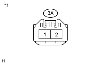
Text in Illustration *1 Front view of wire harness connector
(to Power Distributor (Engine Room Junction Block Assembly))
Disconnect the 3A power distributor (engine room junction block assembly) connector.
-
Measure the voltage according to the value(s) in the table below.
Standard Voltage Tester Connector Condition Specified Condition 3A-1 - Body ground Power switch off 11 to 14 V -
Disconnect the 3C power distributor (engine room junction block assembly) connector.
-
Measure the resistance according to the value(s) in the table below.
Standard Resistance Tester Connection Condition Specified Condition 3C-17 - Body ground Always Below 1 Ω
NG
REPAIR OR REPLACE HARNESS OR CONNECTOR
OK
-
-
CHECK HARNESS AND CONNECTOR (POWER DISTRIBUTOR - INSTRUMENT PANEL JUNCTION BLOCK ASSEMBLY)
-
Disconnect the 2F instrument panel junction block assembly connector.
-
Measure the resistance according to the value(s) in the table below.
Standard Resistance Tester Connection Condition Specified Condition 3C-13 - 2F-37 Always Below 1 Ω 3C-13 - Body ground Always 10 kΩ or higher
NG
REPAIR OR REPLACE HARNESS OR CONNECTOR
OK
-
-
INSPECT INSTRUMENT PANEL JUNCTION BLOCK ASSEMBLY
-
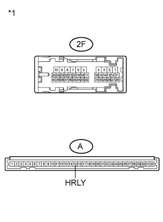
Text in Illustration *1 Component without harness connected
(Instrument Panel Junction Block Assembly)
Remove the instrument panel junction block assembly.
-
Measure the resistance according to the value(s) in the table below.
Standard Resistance Tester Connection Condition Specified Condition 2F-37 - A-15 (HRLY) Always Below 1 Ω 2F-37 - Body ground Always 10 kΩ or higher
NG
REPLACE INSTRUMENT PANEL JUNCTION BLOCK ASSEMBLY Click here
OK
REPLACE MAIN BODY ECU (MULTIPLEX NETWORK BODY ECU) Click here
-
-
INSPECT HEADLIGHT ASSEMBLY
-
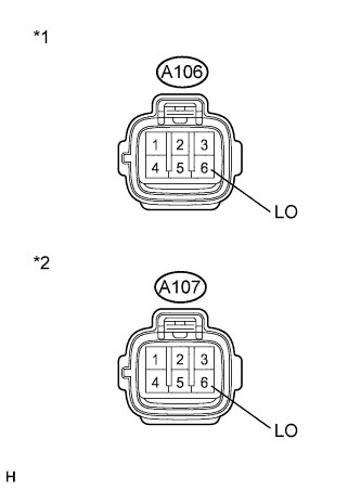
Text in Illustration *1 Front view of wire harness connector
(to Headlight Assembly LH)
*2 Front view of wire harness connector
(to Headlight Assembly RH)
Disconnect the A106 headlight assembly LH connector or A107 headlight assembly RH connector.
-
Measure the voltage according to the value(s) in the table below.
Standard Voltage LH Side (B2430) Tester Connection Switch Condition Specified Condition A106-6 (LO) - Body ground Light control switch in head position 11 to 14 V RH Side (B2431) Tester Connection Switch Condition Specified Condition A107-6 (LO) - Body ground Light control switch in head position 11 to 14 V
NG
CHECK HARNESS AND CONNECTOR (HEADLIGHT ASSEMBLY - POWER DISTRIBUTOR) Click here
OK
-
-
INSPECT HEADLIGHT ASSEMBLY
-
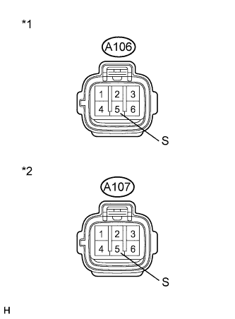
Text in Illustration *1 Front view of wire harness connector
(to Headlight Assembly LH)
*2 Front view of wire harness connector
(to Headlight Assembly RH)
Measure the voltage according to the value(s) in the table below.
Standard Voltage LH Side (B2430) Tester Connection Switch Condition Specified Condition A106-5 (S) - Body ground Power switch on (IG) and light control switch in head position 11 to 14 V RH Side (B2431) Tester Connection Switch Condition Specified Condition A107-5 (S) - Body ground Power switch on (IG) and light control switch in head position 11 to 14 V
NG
CHECK HARNESS AND CONNECTOR (MAIN BODY ECU - HEADLIGHT ASSEMBLY) Click here
OK
-
-
CHECK HARNESS AND CONNECTOR (HEADLIGHT ASSEMBLY - BODY GROUND)
-
Measure the resistance according to the value(s) in the table below.
Standard Resistance LH Side (B2430) Tester Connection Condition Specified Condition A106-4 (E) - Body ground Always Below 1 Ω RH Side (B2431) Tester Connection Condition Specified Condition A107-4 (E) - Body ground Always Below 1 Ω
NG
REPAIR OR REPLACE HARNESS OR CONNECTOR
OK
-
-
REPLACE LIGHT CONTROL ECU
-
Replace the headlight control ECU with a new or normally functioning one Click here.
-
Check for DTCs Click here.
OK DTC B2430 or B2431 is not output.
NG
REPLACE HEADLIGHT UNIT Click here
OK
END
-
-
CHECK HARNESS AND CONNECTOR (HEADLIGHT ASSEMBLY - POWER DISTRIBUTOR)
-
Disconnect the 3B power distributor (engine room junction block assembly) connector.
-
Measure the resistance according to the value(s) in the table below.
Standard Resistance LH Side (B2430) Tester Connection Condition Specified Condition 3B-4 - A106-6 (LO) Always Below 1 Ω 3B-4 - Body ground Always 10 kΩ or higher RH Side (B2431) Tester Connection Condition Specified Condition 3B-3 - A107-6 (LO) Always Below 1 Ω 3B-3 - Body ground Always 10 kΩ or higher
NG
REPAIR OR REPLACE HARNESS OR CONNECTOR
OK
REPLACE POWER DISTRIBUTOR (ENGINE ROOM JUNCTION BLOCK ASSEMBLY) Click here
-
-
CHECK HARNESS AND CONNECTOR (MAIN BODY ECU - HEADLIGHT ASSEMBLY)
-
Disconnect the F14 main body ECU (multiplex network body ECU) connector.
-
Measure the resistance to the according value(s) in the table below.
Standard Resistance LH Side (B2430) Tester Connection Condition Specified Condition F14-21 (LLEW) - A106-5 (S) Always Below 1 Ω F14-21 (LLEW) - Body ground Always 10 kΩ or higher RH Side (B2431) Tester Connection Condition Specified Condition F14-8 (RLEW) - A107-5 (S) Always Below 1 Ω F14-8 (RLEW) - Body ground Always 10 kΩ or higher
NG
REPAIR OR REPLACE HARNESS OR CONNECTOR
OK
REPLACE MAIN BODY ECU (MULTIPLEX NETWORK BODY ECU) Click here
-