INSTRUMENT PANEL SAFETY PAD DISASSEMBLY

-
REMOVE NO. 1 SIDE DEFROSTER NOZZLE DUCT
-
Remove the 2 screws <D> and No. 1 side defroster nozzle duct.
-
-
REMOVE NO. 2 SIDE DEFROSTER NOZZLE DUCT
-
Remove the 2 screws <D> and No. 2 side defroster nozzle duct.
-
-
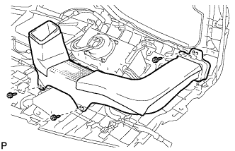
REMOVE DEFROSTER NOZZLE ASSEMBLY
-
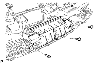
Remove the 3 screws <D> and defroster nozzle assembly.
-
-
REMOVE NO. 1 HEATER TO REGISTER DUCT
-
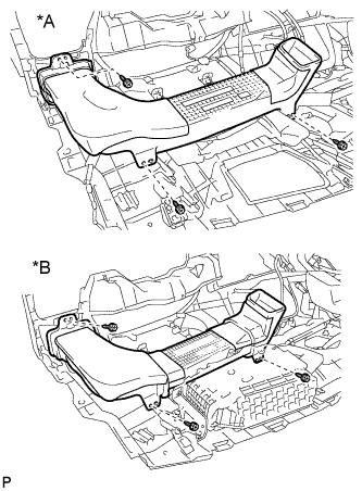
Text in Illustration *A w/o Headup Display *B w/ Headup Display Remove the 3 screws <D> and No. 1 heater to register duct.
-
-
REMOVE NO. 4 HEATER TO REGISTER DUCT
-
Remove the 3 screws <D> and No. 4 heater to register duct.
-
-
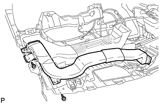
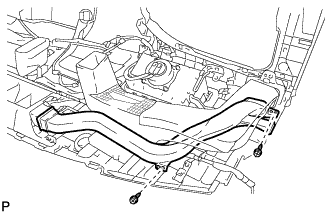
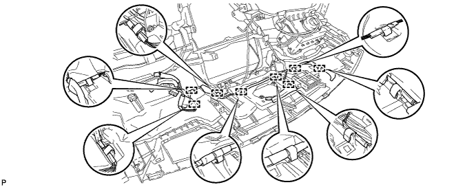
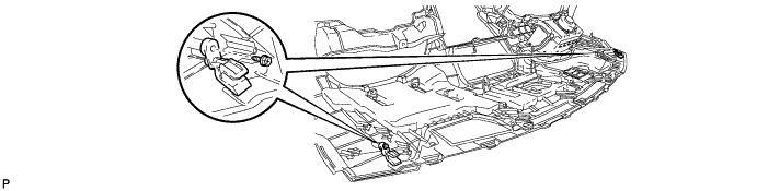
REMOVE NO. 3 INSTRUMENT PANEL WIRE
-
w/ Headup display:
-
Disengage the connector.
-
Disengage the clamp.
-
-
Disengage the 8 clamps and remove the No. 3 instrument panel wire.
-
-
REMOVE NAVIGATION ANTENNA ASSEMBLY (w/ Navigation System)
for LHD: Click here
for RHD: Click here
-
REMOVE NO. 1 METER HOOD RETAINER
-
Remove the 2 screws <D> and 2 No. 1 meter hood retainers.
-
-
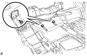
REMOVE NO. 2 INSTRUMENT PANEL MOUNTING BRACKET
-
Remove the 2 screws <D> and 2 No. 2 instrument panel mounting brackets.
-
-
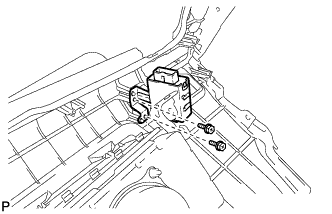
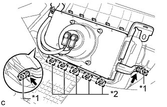
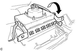
REMOVE MAYDAY BATTERY WITH BRACKET (w/ G-BOOK System)
-
Disconnect the connector.
-
Remove the 2 bolts and mayday battery with bracket.
-
-
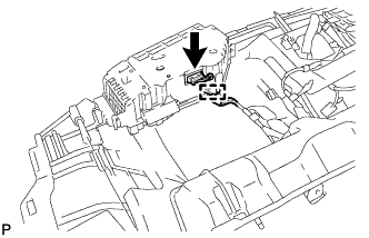
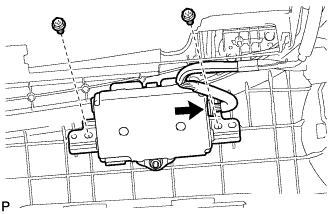
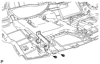
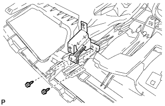
REMOVE DOUBLE LOCK DOOR CONTROL RELAY ASSEMBLY
-
Remove the 2 screws <D> and double lock door control relay assembly.
-
-
REMOVE COMBINATION METER MIRROR ECU (w/ Headup Display)
-
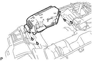
Remove the 4 screws <D> and combination meter mirror ECU.
-
-
REMOVE NO. 1 COMBINATION METER MIRROR BRACKET (w/ Headup Display)
-
Remove the 2 screws <D> and No. 1 combination meter mirror bracket.
-
-
REMOVE NO. 2 COMBINATION METER MIRROR BRACKET (w/ Headup Display)
-
Remove the 2 screws <D> and No. 2 combination meter mirror bracket.
-
-
REMOVE FRONT PASSENGER AIRBAG ASSEMBLY
CAUTION:
When storing the front passenger airbag assembly, keep the airbag deployment side facing upward.
-
Remove the 2 screws and disengage the 2 pins.
-
Lean the instrument panel and disengage the 5 hooks.
Text in Illustration *1 Pin *2 Hook -
Disengage the 5 hooks to remove the front passenger airbag assembly from the instrument panel safety pad assembly as shown in the illustration.
-
-
REMOVE NO. 1 INSTRUMENT PANEL PIN
-
Remove the 2 screws <D> and 2 No. 1 instrument panel pins.
-
-
REMOVE POWER SWITCH
-
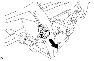
Disengage the 2 claws and remove the power switch as shown in the illustration.
-
-
REMOVE NO. 1 SIDE DEFROSTER NOZZLE
-
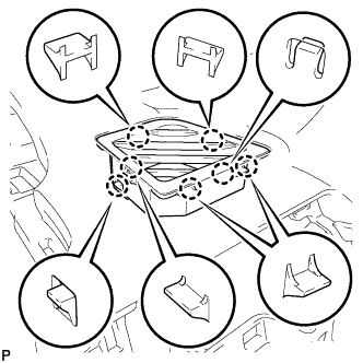
Disengage the 7 claws and remove the No. 1 side defroster nozzle.
-
-
REMOVE NO. 2 SIDE DEFROSTER NOZZLE
Tech Tips
Use the same procedure as for the No. 1 side defroster nozzle.