AIR CONDITIONING UNIT INSTALLATION

-
INSTALL AIR CONDITIONING UNIT ASSEMBLY
-
Install the air conditioning unit assembly with the 3 bolts in the order shown in the illustration.
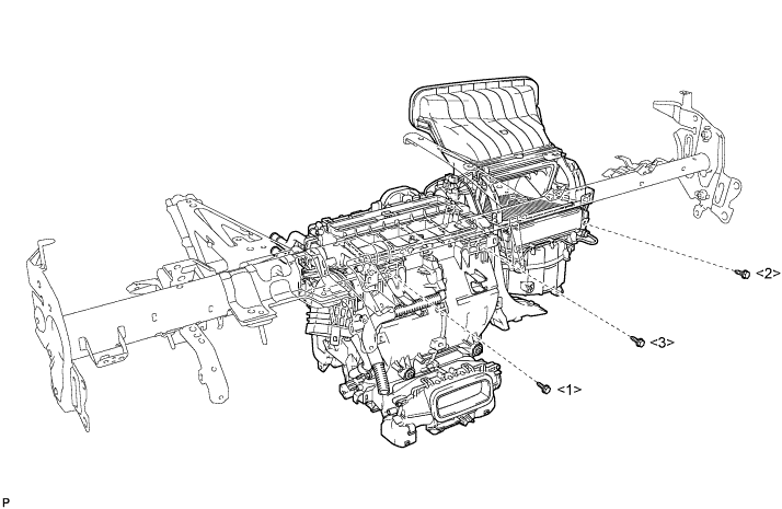
- Torque:
- 9.8 N*m { 100 kgf*cm, 87 in.*lbf }
Note
Tighten the bolts in the order shown in the illustration to install the air conditioning unit assembly.
-
-
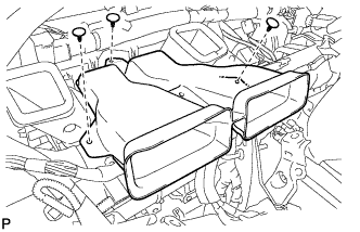
INSTALL NO. 1 AIR DUCT SUB-ASSEMBLY
-
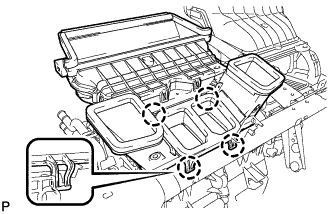
Engage the 4 claws to install the No. 1 air duct sub-assembly.
-
-
INSTALL INSTRUMENT PANEL REINFORCEMENT ASSEMBLY WITH AIR CONDITIONING UNIT ASSEMBLY
-
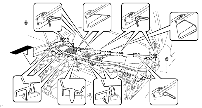
Using a "TORX" socket wrench (T40), install the instrument panel reinforcement assembly with the 5 "TORX" bolts in the order shown in the illustration.
- Torque:
- 20 N*m { 204 kgf*cm, 15 ft.*lbf }
Note
Tighten the bolts in the order shown in the illustration to install the reinforcement assembly.
-
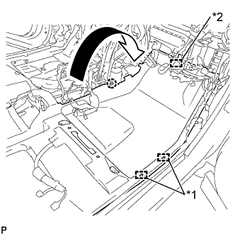
Install the 5 instrument panel safety pad caps.
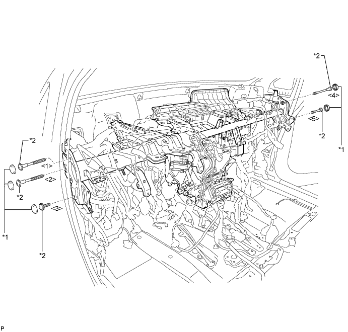
Text in Illustration *1 Instrument Panel Safety Pad Cap *2 "TORX" Bolt -
Install the 2 bolts and 2 caps from to engine compartment side.
- Torque:
- 20 N*m { 204 kgf*cm, 15 ft.*lbf }
-
Install the instrument panel reinforcement assembly with air conditioning unit assembly with the nut.
- Torque:
- 9.8 N*m { 100 kgf*cm, 87 in.*lbf }
-
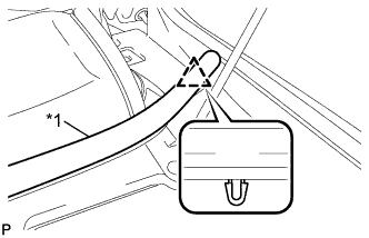
Connect the cooler drain hose as shown in the illustration.
Note
Connect the cooler drain hose firmly to prevent water leaks.
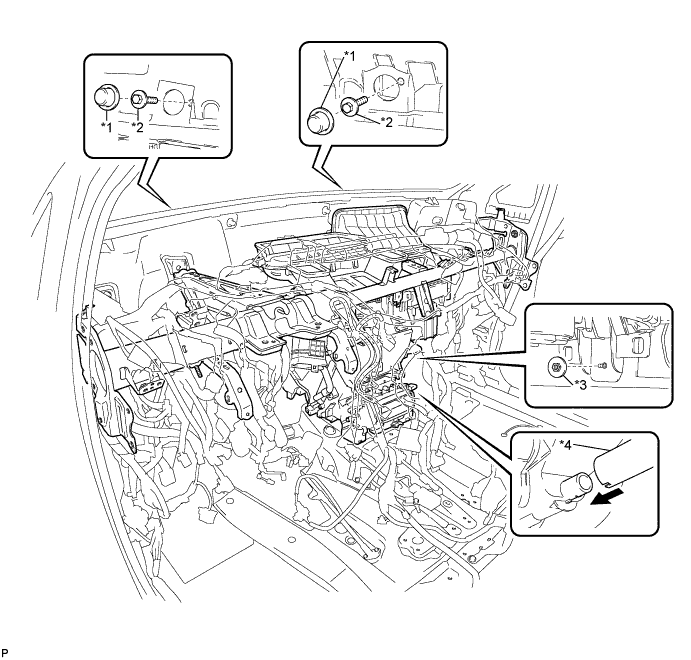
Text in Illustration *1 Cap *2 Bolt *3 Nut *4 Cooler Drain hose -
Engage each clamp.
-
Install the bolt and connect the earth wire.
- Torque:
- 8.4 N*m { 86 kgf*cm, 74 in.*lbf }
-
Connect the connector holder with the nut.
- Torque:
- 5.5 N*m { 56 kgf*cm, 49 in.*lbf }
-
Connect the connector.
-
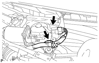
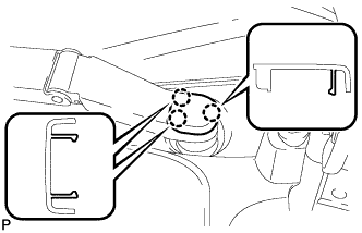
Connect the blower motor connector.
-
Connect the 2 air conditioning ECU connectors.
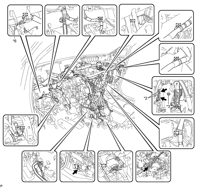
Text in Illustration *1 Blower Motor Connector *2 Air Conditioning ECU Connector *3 Nut *4 Connector Holder *5 Bolt *6 Earth Wire -
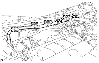
Engage each clamp.
-
Connect the earth wire with the bolt.
- Torque:
- 8.4 N*m { 86 kgf*cm, 74 in.*lbf }
-
Connect each connector.
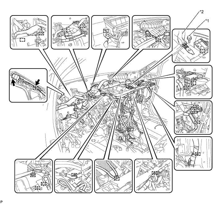
Text in Illustration *1 Bolt *2 Earth Wire
-
-
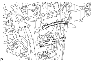
INSTALL NO. 2 INSTRUMENT PANEL BRACE SUB-ASSEMBLY
-
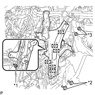
Text in Illustration *1 Screw *2 Bolt *3 Nut Install the 2 bolts and 2 nuts.
- Torque:
- Bolt
- 20 N*m { 204 kgf*cm, 15 ft.*lbf }
- Nut
- 20 N*m { 204 kgf*cm, 15 ft.*lbf }
-
Install the No. 2 instrument panel brace sub-assembly with the screw.
-
Engage each clamp.
-
-
INSTALL NO. 1 INSTRUMENT PANEL BRACE SUB-ASSEMBLY
-
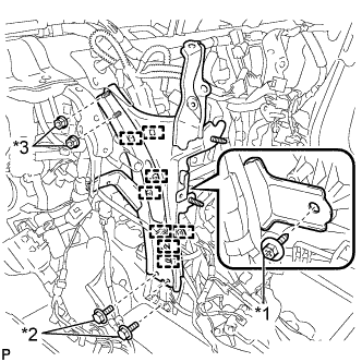
Text in Illustration *1 Screw *2 Bolt *3 Nut Install the 2 bolts and 2 nuts.
- Torque:
- Bolt
- 20 N*m { 204 kgf*cm, 15 ft.*lbf }
- Nut
- 20 N*m { 204 kgf*cm, 15 ft.*lbf }
-
Install the No. 1 instrument panel brace sub-assembly with the screw.
-
Engage each clamp.
-
-
INSTALL NO. 5 INSTRUMENT PANEL BRACKET
-
Install the 2 No. 5 instrument panel brackets.
-
-
INSTALL CENTER HEATER TO REGISTER SUB DUCT
-
Install the center heater to register sub duct with the 3 clips.
-
-
INSTALL REAR NO. 3 AIR DUCT
-
Engage the 2 claws to install the rear No. 3 air duct.
-
-
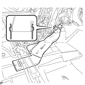
INSTALL REAR NO. 4 AIR DUCT
-
Engage the claw to install the rear No. 4 air duct.
-
Install the clip.
-
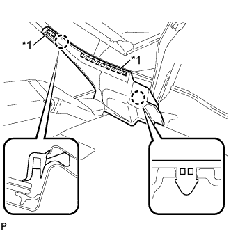
Engage the claw and 2 clamps.
-
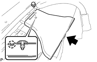
Engage the fastener to install the floor carpet to the original position.
Text in Illustration *1 Clamp *2 Fastener
-
-
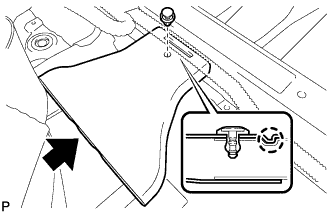
INSTALL FRONT FLOOR CAUTION PLATE COVER
-
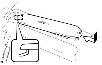
Engage the guide as shown in the illustration.
-
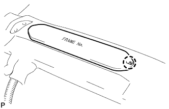
Engage the claw to install the frame number cover.
-
-
INSTALL REAR NO. 1 AIR DUCT
-
Engage the 2 claws to install the rear No. 1 air duct.
-
Engage the clamp.
-
-
INSTALL REAR NO. 2 AIR DUCT
-
Engage the claw to install the rear No. 2 air duct.
-
Install the clip.
-
Engage the claw and 2 clamps.
-
Engage the fastener to install the floor carpet to the original position.
Text in Illustration *1 Clamp *2 Fastener
-
-
INSTALL ECU INTEGRATION BOX
-
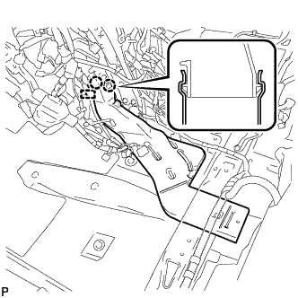
Install the ECU integration box with the bolt and 2 nuts.
- Torque:
- 5.5 N*m { 56 kgf*cm, 49 in.*lbf }
-
-
INSTALL CLEARANCE WARNING BUZZER
-
Engage the clamp to install the clearance warning buzzer.
-
Connect the connector.
-
-
INSTALL TURN SIGNAL FLASHER ASSEMBLY
-
Connect the connector.
-
Engage the clamp to install the turn signal flasher assembly.
-
-
INSTALL POWER STEERING ECU ASSEMBLY
for LHD Click here
for RHD Click here
-
INSTALL INSTRUMENT PANEL JUNCTION BLOCK ASSEMBLY (for LHD)
-
Engage the claw to connect the connector as shown in the illustration.
-
Engage the 2 claws to lock the connector lock as shown in the illustration.
-
Engage the claw to connect the connector as shown in the illustration.
-
Install the instrument panel junction block assembly with the 2 nuts.
- Torque:
- 8.0 N*m { 82 kgf*cm, 71 in.*lbf }
-
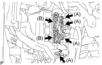
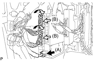
Connect the 4 connectors (A).
-
Engage the 2 claws to connect the 2 connectors (B).
-
Connect the 4 connectors.
-
-
INSTALL INSTRUMENT PANEL JUNCTION BLOCK ASSEMBLY (for RHD)
-
Engage the claw to connect the connector as shown in the illustration.
-
Engage the 2 claws to lock the connector lock as shown in the illustration.
-
Engage the claw to connect the connector as shown in the illustration.
-
Install the instrument panel junction block assembly with the bolt and nut.
- Torque:
- Bolt
- 13 N*m { 127 kgf*cm, 9 ft.*lbf }
- Nut
- 8.0 N*m { 82 kgf*cm, 71 in.*lbf }
-
Connect the connector (A).
-
Engage the 2 claws to connect the 2 connectors (B) as shown in the illustration.
-
Connect the 3 connectors.
-
-
INSTALL STEERING POST ASSEMBLY
-
INSTALL INSTRUMENT PANEL SAFETY PAD ASSEMBLY
-
CONNECT INLET HEATER WATER HOSE
-
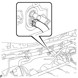
Using pliers, grip the claws of the clip and slide the clip to connect the inlet heater water hose.
-
-
CONNECT OUTLET HEATER WATER HOSE
-
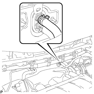
Using pliers, grip the claws of the clip and slide the clip to connect the outlet heater water hose.
-
-
CONNECT AIR CONDITIONING TUBE AND ACCESSORY ASSEMBLY
-
Remove the attached vinyl tape from the pipe.
-
Sufficiently apply compressor oil to a new O-ring and the fitting surface of the air conditioning tube and accessory assembly.
Compressor oil ND-OIL 11 or equivalent -
Install the O-ring on the air conditioning tube and accessory assembly.
Note
-
Keep the O-ring and O-ring fitting surfaces clean from dirt or any foreign objects.
-
Do not use any compressor oil other than ND-OIL 11 or equivalent. If any compressor oil other than ND-OIL 11 or equivalent is used, compressor motor insulation performance may decrease, resulting in a leakage of electric power.
-
-
Install the air conditioning tube and accessory assembly.
-
-
CONNECT SUCTION PIPE SUB-ASSEMBLY
-
Remove the attached vinyl tape from the pipe.
-
Sufficiently apply compressor oil to a new O-ring and the fitting surface of the suction pipe sub-assembly.
Compressor oil ND-OIL 11 or equivalent -
Install the O-ring on the suction pipe sub-assembly.
Note
-
Keep the O-ring and O-ring fitting surfaces clean from dirt or any foreign objects.
-
Do not use any compressor oil other than ND-OIL 11 or equivalent. If any compressor oil other than ND-OIL 11 or equivalent is used, compressor motor insulation performance may decrease, resulting in a leakage of electric power.
-
-
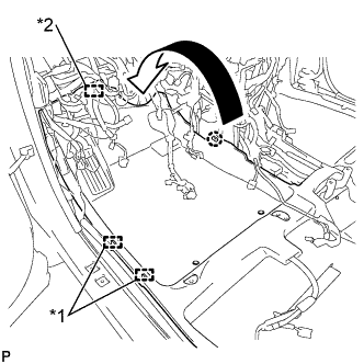
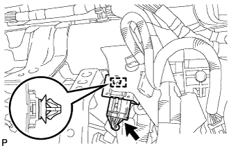
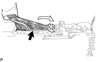
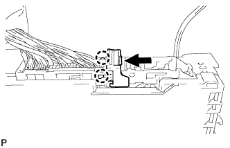
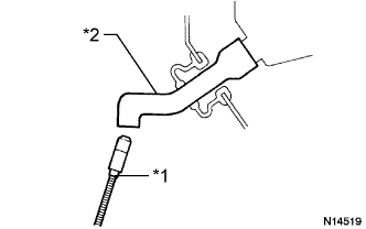
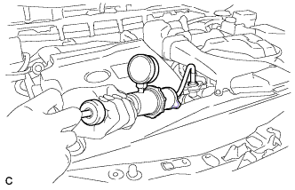
Install the suction pipe sub-assembly.
-
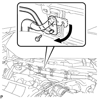
Move the hook connector in the direction indicated by the arrow in the illustration.
-
Insert the pipe joint into the fitting hole securely and tighten the bolt.
- Torque:
- 9.8 N*m { 100 kgf*cm, 87 in.*lbf }
-
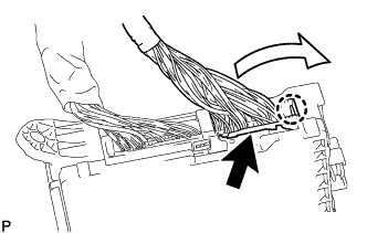
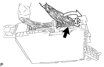
Engage the 6 clamps to the engine wire harness.
-
-
INSTALL OUTER COWL TOP PANEL SUB-ASSEMBLY
for LHD Click here
for RHD Click here
-
INSTALL FRONT SHOCK ABSORBER CAP LH (w/ Air Suspension)
-
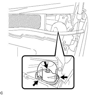
Install the front shock absorber cap with the 3 nuts.
- Torque:
- 14 N*m { 143 kgf*cm, 10 ft.*lbf }
-
-
INSTALL FRONT SHOCK ABSORBER CAP RH (w/ Air Suspension)
Tech Tips
Use the same procedure for the RH side and LH side.
-
INSTALL WINDSHIELD WIPER MOTOR AND LINK ASSEMBLY
-
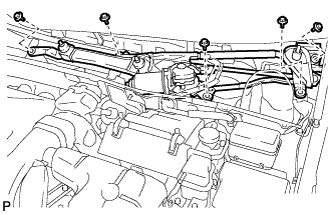
Install the windshield wiper motor and link assembly with the 5 bolts.
- Torque:
- 7.0 N*m { 71 kgf*cm, 62 in.*lbf }
Note
Be careful not to damage the windshield when installing the windshield wiper motor and link assembly.
-
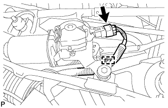
w/o Deicer:
-
Engage the clamp.
-
Connect the connector.
-
-
w/ Deicer:
-
Engage the clamp.
-
Connect each connector.
-
-
-
INSTALL COWL TOP VENTILATOR LOUVER SUB-ASSEMBLY
-
Engage the 10 guides.
-
Engage the 6 claws and guide <A> as shown in the illustration.
-
Install the 2 clips to cowl top ventilator louver sub-assembly.
-
-
INSTALL FRONT WIPER ARM AND BLADE ASSEMBLY RH
-
Operate the wiper and stop the windshield wiper motor at the automatic stop position.
-

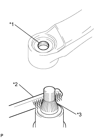
Text in Illustration *1 Wiper Arm Serration *2 Wire Brush *3 Wiper Pivot Serration When reusing the front wiper arm and blade assembly RH:
-
Clean the wiper arm serrations.
-
-
When reusing the windshield wiper link assembly:
-
Clean the wiper pivot serrations with a wire brush.
-
-
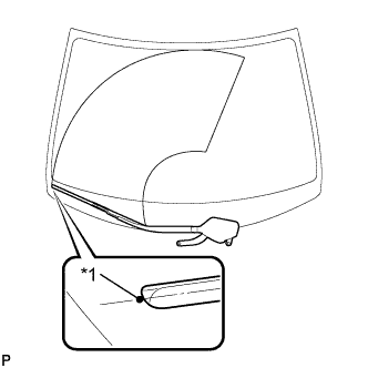
Text in Illustration *1 Ceramic Dot Install the front wiper arm and blade assembly RH with the 2 nuts to the position shown in the illustration.
- Torque:
- 24 N*m { 245 kgf*cm, 18 ft.*lbf }
Tech Tips
While holding the tip of the wiper blade on the glass at approximately 20 mm above the ceramic dot, press down on the wiper arm and tighten the nut. Then raise and lower the wiper arm a few times to confirm that it has settled to the specified position.
-
-
INSTALL FRONT WIPER ARM AND BLADE ASSEMBLY LH
-
Text in Illustration *1 Wiper Arm Serration *2 Wire Brush *3 Wiper Pivot Serration When reusing the front wiper arm and blade assembly LH:
-
Clean the wiper arm serrations.
-
-
When reusing the windshield wiper link assembly:
-
Clean the wiper pivot serrations with a wire brush.
-
-
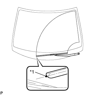
Text in Illustration *1 Ceramic Dot Install the front wiper arm and blade assembly LH with the nut to the position shown in the illustration.
- Torque:
- 24 N*m { 245 kgf*cm, 18 ft.*lbf }
Tech Tips
Hold the wiper arm by hand while tightening the nut.
-
Operate the front wipers while spraying washer fluid on the windshield glass. Make sure that the front wipers function properly and there is no interference with the vehicle body.
-
-
INSTALL FRONT WIPER ARM HEAD CAP
-
Engage the 3 claws to install the front wiper arm head cap.
-
-
INSTALL FRONT FENDER TO COWL SIDE SEAL LH
-
Wipe off any tape adhesive residue with cleaner.
-
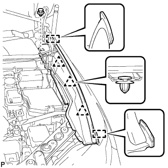
Text in Illustration *1 Double-sided Tape Engage the 2 claws and install a new front fender to cowl side seal LH.
-
-
INSTALL FRONT FENDER TO COWL SIDE SEAL RH
Tech Tips
Use the same procedure for the RH side and LH side.
-
INSTALL FRONT FENDER TOP REINFORCEMENT SUB-ASSEMBLY LH
-
Engage the 3 clips and 2 guides.
-
Install the front fender top reinforcement sub-assembly LH with the clip.
-
Text in Illustration *1 Hood to Cowl Top Seal Engage the clip to the hood to cowl top seal to the front fender top reinforcement sub-assembly LH.
-
-
INSTALL FRONT FENDER TOP REINFORCEMENT SUB-ASSEMBLY RH
Tech Tips
Use the same procedure for the RH side and LH side.
-
INSTALL FRONT SEAT ASSEMBLY
-
for LH Side: Click here
-
for RH Side:
Tech Tips
Use the same procedure for the RH side and LH side.
-
-
ADD COOLANT (for Engine)
-
Tighten the radiator drain cock plug by hand.
-
Tighten the cylinder block drain cock plug. (for Bank 1)
- Torque:
- 13 N*m { 130 kgf*cm, 9 ft.*lbf }
-
Tighten the cylinder block drain cock plug. (for Bank 2, w/ Cylinder Block Drain Cock Plug)
- Torque:
- 13 N*m { 130 kgf*cm, 9 ft.*lbf }
-
Loosen the air drain cock plug on the water inlet housing.
-
Add engine coolant to the radiator inlet opening until engine coolant overflows from the air drain cock hole. Then tighten the air drain cock plug to the water inlet housing.
- Torque:
- 13 N*m { 130 kgf*cm, 9 ft.*lbf }
-
Slowly fill the radiator assembly with engine coolant.
Standard Capacity Item Capacity Engine coolant 11.7 liters (12.4 US qts, 10.2 lmp. qts) Note
Never use water as a substitute for engine coolant.
Tech Tips
TOYOTA vehicles are filled with TOYOTA SLLC at the factory. In order to avoid damage to the engine cooling system and other technical problems, only use TOYOTA SLLC or similar high quality ethylene glycol based non-silicate, non-amine, non-nitrite, non-borate coolant with long-life hybrid organic acid technology (coolant with long-life hybrid organic acid technology is a combination of low phosphates and organic acids).
-
Remove the reserve tank cap.
-
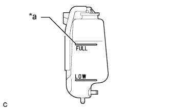
Text in Illustration *a Full Line Slowly pour engine coolant into the radiator reserve tank assembly until it reaches the full line.
-
Squeeze the No. 1 radiator hose and No. 2 radiator hose several times by hand, and then check the level of the engine coolant.
If the engine coolant level is low, add engine coolant.
-
Install the radiator cap sub-assembly and reserve tank cap.
-
Bleed air from the cooling system.
-
Put the engine in inspection mode Click here.
-
Warm up the engine until the thermostat opens. While the thermostat is open, circulate the engine coolant for several minutes.
Tech Tips
The thermostat open timing can be confirmed by squeezing the No. 2 radiator hose by hand, and sensing vibrations when the engine coolant starts to flow inside the No. 2 radiator hose.
-
Maintain the engine speed at 2500 rpm.
-
Squeeze the No. 1 radiator hose and No. 2 radiator hose several times by hand to bleed air.
CAUTION:
When squeezing the No. 1 radiator hose and No. 2 radiator hose:
-
Wear protective gloves.
-
Be careful as the No. 1 radiator hose and No. 2 radiator hose are hot.
-
Keep your hands away from the fan and No. 2 fan.
Note
-
If the coolant temperature gauge indicates an excessive temperature, turn off the engine and let it cool.
-
Make sure that the radiator reserve tank assembly still has some engine coolant in it.
-
If the radiator reserve tank assembly does not have enough engine coolant, the engine may overheat or be seriously damaged.
-
If the radiator reserve tank assembly does not have enough engine coolant, perform the following: 1) stop the engine, 2) wait until the engine coolant has cooled down, and 3) add engine coolant until the radiator reserve tank assembly is filled to the full line.
-
-
-
Stop the engine, and wait until the engine coolant cools down.
-
Add engine coolant to the full line on the radiator reserve tank assembly.
-
-
CHARGE WITH REFRIGERANT
-
Perform vacuum purging using a vacuum pump.
-
Charge with refrigerant HFC-134a (R134a).
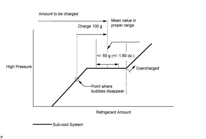
Standard 550 to 650 g (19.4 to 22.9 oz.) - SST
- 09985-20010 ( 09985-02010, 09985-02050, 09985-02060, 09985-02070, 09985-02080, 09985-02090, 09985-02110, 09985-02130, 09985-02140, 09985-02150 )
Note
-
Do not turn the A/C on before charging with refrigerant. Doing so will cause the compressor to work without refrigerant, resulting in overheating of the cooler compressor.
-
Approximately 100 g (3.53 oz.) of refrigerant may need to be charged after bubbles disappear. The refrigerant amount should be checked by quantity, not with the sight glass.
-
Avoid using the gauge manifold set that had been used for vehicles with conventional compressor oil (ND-OIL 8 or equivalent) as much as possible. This will cause compressor oil remaining in the manifold to enter the vehicle, resulting in insulation performance deterioration. A gauge manifold set that had been used 3 times or less can be reused if an appropriate one is not available.
Tech Tips
Ensure that sufficient refrigerant is available to recharge the system when using a refrigerant recovery unit. Refrigerant recovery units are not always able to recover 100% of the refrigerant from an A/C system.
-
-
WARM UP COMPRESSOR
-
Keep the A/C switch on for at least 2 minutes to warm up the compressor.
Note
Be sure to warm up the compressor when turning the A/C on after removing and installing the cooler refrigerant lines (including the compressor), to prevent damage to the compressor.
-
-
INSPECT FOR REFRIGERANT LEAK
-
After recharging with refrigerant, inspect for refrigerant leaks using a halogen leak detector.
-
Carry out the test under the following conditions:
-
Turn the power switch off.
-
Secure good ventilation (the halogen leak detector may react to volatile gases which are not refrigerant, such as evaporated gasoline and exhaust gas).
-
Repeat the test 2 or 3 times.
-
Make sure that there is some refrigerant remaining in the refrigeration system.
When the compressor is off: approx. 392 to 588 kPa (4 to 6 kgf/cm2, 57 to 85 psi)
-
-
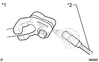
Text in Illustration *1 Inspect for Leak *2 Halogen Leak Detector Using a halogen leak detector, inspect for refrigerant leaks from the refrigerant lines.
-
Text in Illustration *1 Halogen Leak Detector *2 Drain Hose Bring the halogen leak detector close to the drain hose with the detector's power off, and then turn the detector on.
Tech Tips
-
After the blower motor has stopped, let the cooling unit stand for more than 15 minutes.
-
Bring the halogen leak detector sensor under the drain hose.
-
When bringing the halogen leak detector close to the drain hose, make sure that the halogen leak detector does not react to volatile gases. If it is not possible to avoid interference from volatile gases, the vehicle should be lifted up to allow testing.
-
-
If a refrigerant leak is not detected from the drain hose, remove the blower motor control from the cooling unit. Insert the halogen leak detector sensor into the unit and perform the test.
-
Disconnect the pressure switch connector and leave it for approximately 20 minutes. Bring the halogen leak detector close to the pressure switch and perform the test.
-
-
INSPECT FOR COOLANT LEAK (for Engine)
CAUTION:
Do not remove the radiator cap while the engine and radiator are still hot. Pressurized hot engine coolant and steam may be released and cause serious burns.
Note
Before performing each inspection, turn the A/C switch off.
-
Remove the radiator cap.
-
Fill the radiator with coolant and attach a radiator cap tester.
-
Put the engine in inspection mode Click here.
-
Warm up the engine.
-
Using the radiator cap tester, increase the pressure inside the radiator to 118 kPa (1.2 kgf/cm2, 17 psi), and check that the pressure does not drop.
If the pressure drops, check the hoses, radiator, exhaust center pipe assembly and the heater hose around the water temperature switch and engine water pump for leaks. If no external leaks are found, check the heater core, cylinder block and cylinder head.
-
Remove the radiator cap tester.
-
Install the radiator cap.
-
-
INSTALL COOL AIR INTAKE DUCT SEAL
-
Install the cool air intake duct seal with the 6 clips.
-
-
INSTALL ENGINE ROOM SIDE COVER
-
Install the engine room side cover with the 4 clips.
-
-
INSTALL ENGINE ROOM SIDE COVER LH
-
Engage the guide.
-
Install the engine room side cover LH with the 4 clips.
-
-
INITIALIZE SERVO MOTOR
-
Turn the power switch off.
-
Connect the intelligent tester to the DLC3.
-
Turn the power switch on (IG).
-
Press the A/C OFF switch.
-
Turn the intelligent tester on.
-
Enter the following menus: Body / Air Conditioner / Utility / Servomotor Initialization.
-
According to the intelligent tester display, select the "Next" switch.
-
According to the intelligent tester display, select the "Next" switch.
Tech Tips
During initialization, the AUTO indicator illuminates. When initialization is complete, the indicator turns off.
-
According to the intelligent tester display, select the exit to finish the initialization.
-