Click here
-
DESCRIPTION
-
Air conditioning system data and Diagnostic Trouble Codes (DTCs) can be read through the Data Link Connector 3 (DLC3) of the vehicle. When the system seems to be malfunctioning, use the intelligent tester to check for malfunctions and perform troubleshooting.
-
-
CHECK DLC3
-
Check the DLC3 (Click here).
-
-
LIST OF OPERATION METHODS
-
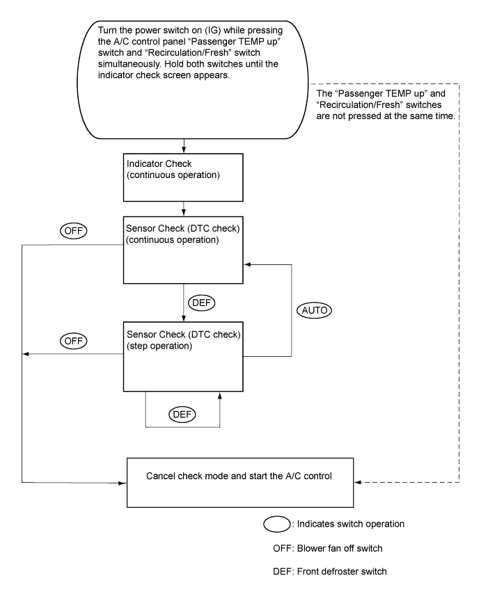
By operating each of the air conditioning control switches as shown in the diagram below, it is possible to enter diagnostic check mode.
-
-
INDICATOR CHECK
-
Turn the power switch off.
-
Turn the power switch on (ACC) and wait at least 5 seconds.
-
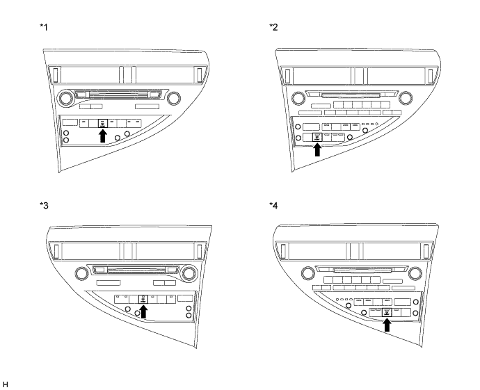
Turn the power switch on (IG) while pressing the A/C control panel "Passenger TEMP up" switch and "Recirculation/Fresh" switch simultaneously. Hold both switches until the indicator check screen appears.
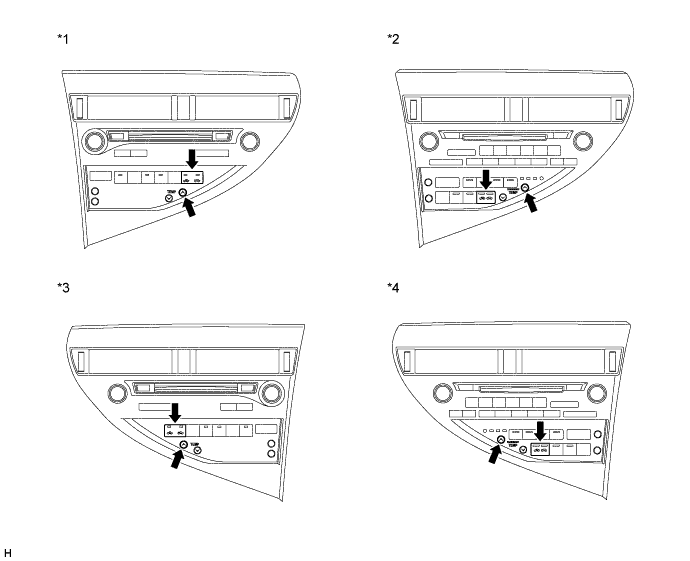
Table 1. Text in Illustration *1 Multi-media Module Receiver Assembly (w/ Navigation System) or Radio Receiver Assembly (w/ Audio and Visual System (w/ Multi-display))
(for LHD)
*2 Radio Receiver Assembly (w/ Audio and Visual System (w/o Multi-display))
(for LHD)
*3 Multi-media Module Receiver Assembly (w/ Navigation System)
(for RHD)
*4 Radio Receiver Assembly (w/ Audio and Visual System (w/o Multi-display))
(for RHD)
-
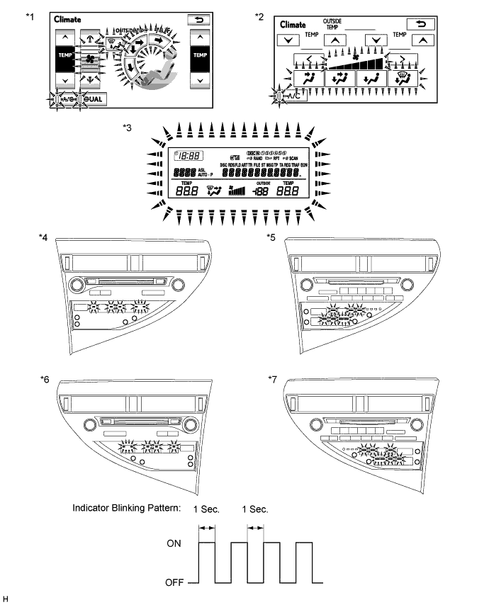
The indicator check is automatically performed when panel diagnosis is activated. Check that the indicators light up and go off 4 times at 1-second intervals.
Tip:
-
The sensor check automatically starts when the indicator check is completed.
-
Press the "OFF" switch to cancel check mode.
Table 2. Text in Illustration *1 Multi-display Assembly (w/ Navigation System) *2 Multi-display Assembly (w/ Audio and Visual System (w/ Multi-display)) *3 Accessory Meter Assembly (w/o Multi-display) *4 Multi-media Module Receiver Assembly (w/ Navigation System) or Radio Receiver Assembly (w/ Audio and Visual System (w/ Multi-display))
(for LHD)
*5 Radio Receiver Assembly (w/ Audio and Visual System (w/o Multi-display))
(for LHD)
*6 Multi-media Module Receiver Assembly (w/ Navigation System)
(for RHD)
*7 Radio Receiver Assembly (w/ Audio and Visual System (w/o Multi-display))
(for RHD)
- - -
-
-
SENSOR CHECK (DTC CHECK)
-
Start the hybrid system and warm it up.
-
Perform the indicator check.
Tip:After the indicator check is completed, the system enters DTC check mode automatically.
-
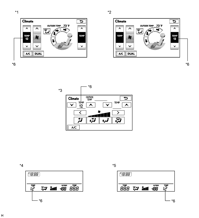
Read the DTC displayed on the multi-display assembly*1 or the accessory meter assembly*2.
Note:In sensor check mode, which is automatically entered after indicator check mode, troubleshooting may be partially performed. Be sure to perform the sensor check again.
Tip:Refer to Diagnostic Trouble Code Chart for details of the codes (Click here).
-
When there are no problems, DTC 00 is output.
-
As an example, the illustration shows that display DTC 12 is output.
-
*1: w/ Multi-display
-
*2: w/o Multi-display
Table 3. Text in Illustration *1 Multi-display Assembly (w/ Navigation System)
(for LHD)
*2 Multi-display Assembly (w/ Navigation System)
(for RHD)
*3 Multi-display Assembly (w/ Audio and Visual System (w/ Multi-display)) *4 Accessory Meter Assembly (w/o Multi-display)
(for LHD)
*5 Accessory Meter Assembly (w/o Multi-display)
(for RHD)
*6 Diagnostic Trouble Code (DTC) -
-
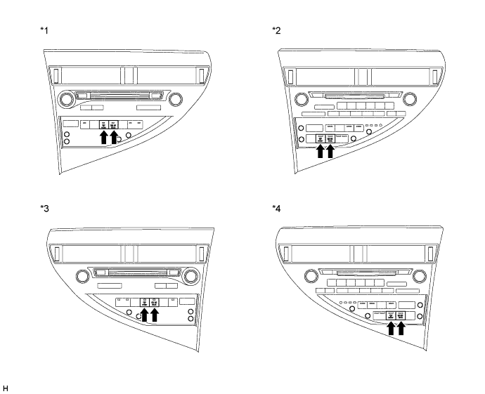
If the steps are difficult to read because they change automatically, press the "FRONT DEF" switch to display the steps one at a time so that they can be read easily. The items are displayed step by step each time the "FRONT DEF" switch is pressed.
Tip:Press the "OFF" switch to finish panel diagnosis.
Table 4. Text in Illustration *1 Multi-media Module Receiver Assembly (w/ Navigation System) or Radio Receiver Assembly (w/ Audio and Visual System (w/ Multi-display))
(for LHD)
*2 Radio Receiver Assembly (w/ Audio and Visual System (w/o Multi-display))
(for LHD)
*3 Multi-media Module Receiver Assembly (w/ Navigation System)
(for RHD)
*4 Radio Receiver Assembly (w/ Audio and Visual System (w/o Multi-display))
(for RHD)
-
Clear the DTC
-
During the sensor check, press the "FRONT DEF" switch and "REAR DEF" switch simultaneously.
Table 5. Text in Illustration *1 Multi-media Module Receiver Assembly (w/ Navigation System) or Radio Receiver Assembly (w/ Audio and Visual System (w/ Multi-display))
(for LHD)
*2 Radio Receiver Assembly (w/ Audio and Visual System (w/o Multi-display))
(for LHD)
*3 Multi-media Module Receiver Assembly (w/ Navigation System)
(for RHD)
*4 Radio Receiver Assembly (w/ Audio and Visual System (w/o Multi-display))
(for RHD)
-
-