Make sure to select FACE mode before disconnecting the cable from the auxiliary battery negative (-) terminal.
- Click here
RECOVER REFRIGERANT FROM REFRIGERATION SYSTEM
-
Turn the A/C switch on.
-
Operate the A/C with the setting temperature at 25°C (77°F) and the blower level at LO for 10 minutes to circulate the refrigerant. This causes most of the compressor oil from the various components of the A/C system to collect in the A/C compressor.
-
Turn the power switch off.
-
Recover the refrigerant from the A/C system using a refrigerant recovery unit.
-
- Click here
REMOVE FRONT SEAT ASSEMBLY
-
for LH Side: (Click here)
-
for RH Side:
Tip:Use the same procedure for the RH side and LH side.
-
- Click here
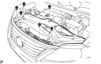
REMOVE ENGINE ROOM SIDE COVER
-
Remove the 4 clips and engine room side cover.
-
- Click here
REMOVE ENGINE ROOM SIDE COVER LH
-
Remove the 4 clips.
-
Disengage the guide and remove the engine room side cover LH.
-
- Click here
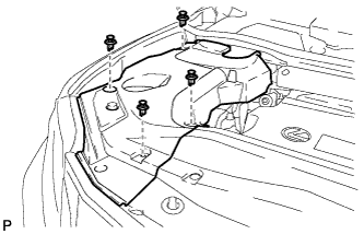
REMOVE COOL AIR INTAKE DUCT SEAL
-
Remove the 6 clips and cool air intake duct seal.
-
- Click here
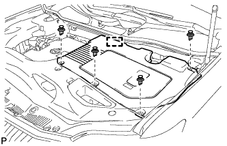
REMOVE FRONT FENDER TOP REINFORCEMENT SUB-ASSEMBLY LH
-
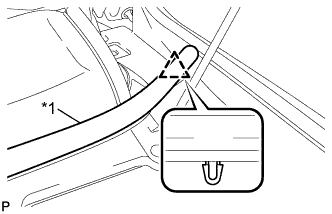
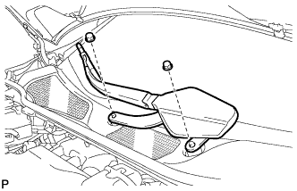
Disengage the clip and the hood to cowl top seal from the front fender top reinforcement sub-assembly LH.
Table 1. Text in Illustration *1 Hood to Cowl Top Seal -
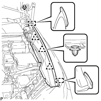
Remove the clip.
-
Disengage the 3 clips and 2 guides, and remove the front fender top reinforcement sub-assembly LH.
-
- Click here
REMOVE FRONT FENDER TOP REINFORCEMENT SUB-ASSEMBLY RH
Tip:Use the same procedure for the RH side and LH side.
- Click here
REMOVE FRONT FENDER TO COWL SIDE SEAL LH
-
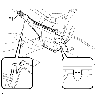
Disengage the 2 claws and remove the front fender to cowl side seal LH.
Table 2. Text in Illustration *1 Double-sided Tape
-
- Click here
REMOVE FRONT FENDER TO COWL SIDE SEAL RH
Tip:Use the same procedure for the RH side and LH side.
- Click here
REMOVE FRONT WIPER ARM HEAD CAP
-
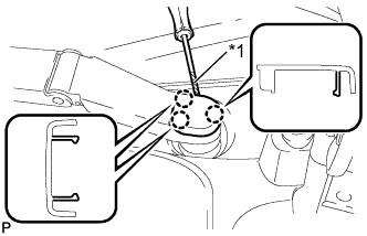
Using a screwdriver, disengage the 3 claws and remove the front wiper arm head cap.
Table 3. Text in Illustration *1 Protective Tape Tip:Tape the screwdriver tip before use.
-
- Click here
REMOVE FRONT WIPER ARM AND BLADE ASSEMBLY LH
-
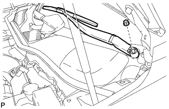
Remove the nut and the front wiper arm and blade assembly LH.
-
- Click here
REMOVE FRONT WIPER ARM AND BLADE ASSEMBLY RH
-
Remove the 2 nuts and the front wiper arm and blade assembly RH.
-
- Click here
REMOVE COWL TOP VENTILATOR LOUVER SUB-ASSEMBLY
-
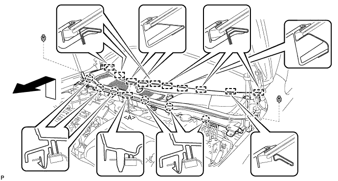
Remove the 2 clips.
-
Disengage the 6 claws and guide <A>.
-
Disengage the 10 guides and pull out the cowl top ventilator louver sub-assembly as shown in the illustration.
-
- Click here
REMOVE WINDSHIELD WIPER MOTOR AND LINK ASSEMBLY
-
Operate the wiper and stop the windshield wiper motor at the automatic stop position.
-
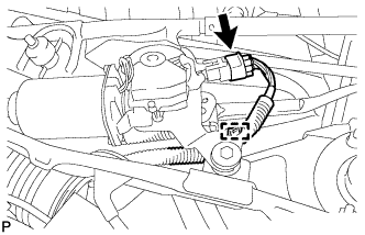
w/o Deicer:
-
Disconnect the connector.
-
Disengage the clamp.
-
-
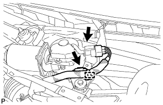
w/ Deicer:
-
Disconnect the 2 connectors.
-
Disengage the clamp.
-
-
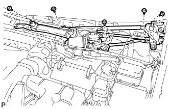
Remove the 5 bolts and the windshield wiper motor and link assembly.
Note:Be careful not to damage the windshield when removing the windshield wiper motor and link assembly.
-
- Click here
REMOVE FRONT SHOCK ABSORBER CAP LH (w/ Air Suspension)
-
Remove the 3 nuts and front shock absorber cap.
-
- Click here
REMOVE FRONT SHOCK ABSORBER CAP RH (w/ Air Suspension)
Tip:Use the same procedure for the RH side and LH side.
- Click here
REMOVE OUTER COWL TOP PANEL SUB-ASSEMBLY
for LHD: (Click here)
for RHD: (Click here)
- Click here
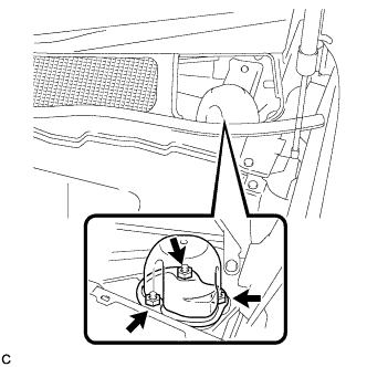
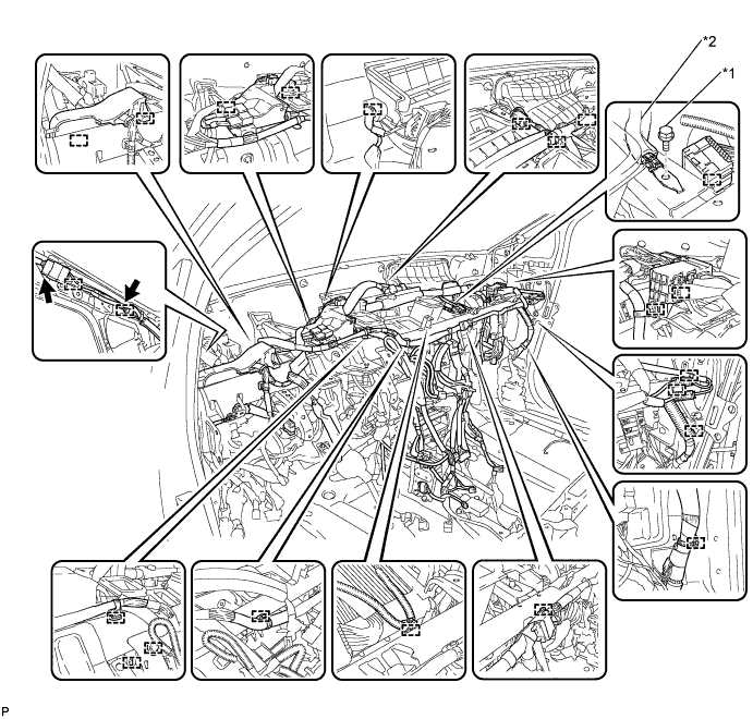
DISCONNECT SUCTION PIPE SUB-ASSEMBLY
-
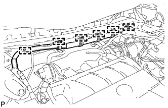
Disengage the 6 clamps and separate the engine wire harness.
-
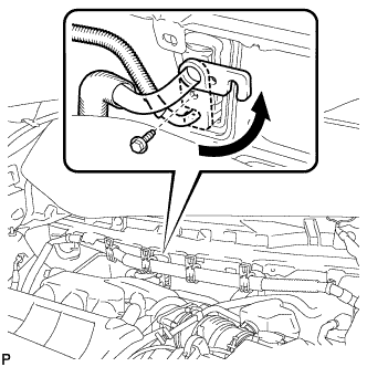
Remove the bolt and slide the hook connector.
-
Disconnect the suction pipe assembly.
-
Remove the O-ring from the suction pipe assembly.
Note:Seal the openings of the disconnected parts using vinyl tape to prevent entry of moisture and foreign matter.
-
- Click here
DISCONNECT AIR CONDITIONING TUBE AND ACCESSORY ASSEMBLY
-
Disconnect the air conditioning tube and accessory assembly.
-
Remove the O-ring from the air conditioning tube and accessory assembly.
Note:Seal the openings of the disconnected parts using vinyl tape to prevent entry of moisture and foreign matter.
-
- Click here
DISCONNECT OUTLET HEATER WATER HOSE
-
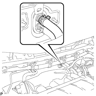
Using pliers, grip the claws of the clip and slide the clip to disconnect the outlet heater water hose.
Note:
-
Do not apply excessive force to the outlet heater water hose.
-
Prepare a drain pan or cloth in case the coolant leaks.
-
-
- Click here
DISCONNECT INLET HEATER WATER HOSE
-
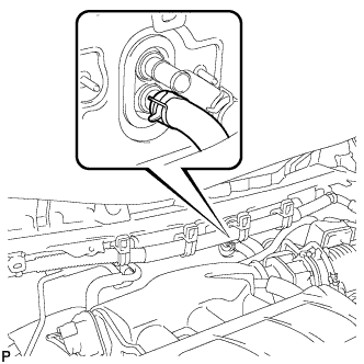
Using pliers, grip the claws of the clip and slide the clip to disconnect the inlet heater water hose.
Note:
-
Do not apply excessive force to the inlet heater water hose.
-
Prepare a drain pan or cloth in case the coolant leaks.
-
-
- Click here
REMOVE INSTRUMENT PANEL SAFETY PAD ASSEMBLY
- Click here
REMOVE STEERING POST ASSEMBLY
- Click here
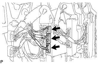
REMOVE INSTRUMENT PANEL JUNCTION BLOCK ASSEMBLY (for LHD)
-
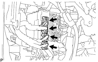
Disconnect the 4 connectors.
-
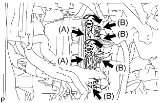
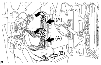
Disengage the 2 claws as shown in the illustration and disconnect the 2 connectors (A).
-
Disconnect the 4 connectors (B).
-
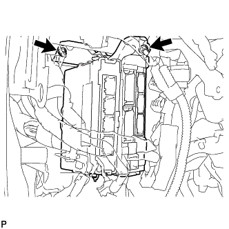
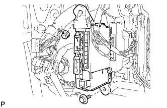
Remove the 2 nuts.
-
Disengage the claw as shown in the illustration and disconnect the connector.
-
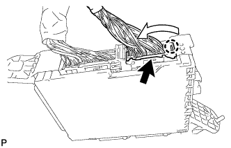
Disengage the 2 claws and release the connector lock as shown in the illustration.
-
Disengage the claw as shown in the illustration and disconnect the connector and remove the instrument panel junction block assembly.
-
- Click here
REMOVE INSTRUMENT PANEL JUNCTION BLOCK ASSEMBLY (for RHD)
-
Disconnect the 3 connectors.
-
Disengage the 2 claws as shown in the illustration and disconnect the 2 connectors (A).
-
Disconnect the connector (B).
-
Remove the bolt and nut.
-
Disengage the claw as shown in the illustration and disconnect the connector.
-
Disengage the 2 claws and release the connector lock as shown in the illustration.
-
Disengage the claw as shown in the illustration and disconnect the connector and remove the instrument panel junction block assembly.
-
- Click here
REMOVE POWER STEERING ECU ASSEMBLY
for LHD: (Click here)
for RHD: (Click here)
- Click here
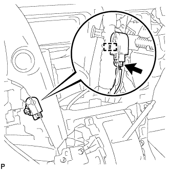
REMOVE TURN SIGNAL FLASHER ASSEMBLY
-
Disengage the clamp.
-
Disconnect the connector and remove the turn signal flasher assembly.
-
- Click here
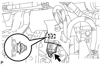
REMOVE CLEARANCE WARNING BUZZER
-
Disconnect the connector.
-
Disengage the clamp and remove the clearance warning buzzer.
-
- Click here
REMOVE ECU INTEGRATION BOX
-
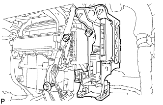
Remove the bolt, 2 nuts and ECU integration box.
-
- Click here
REMOVE REAR NO. 2 AIR DUCT
-
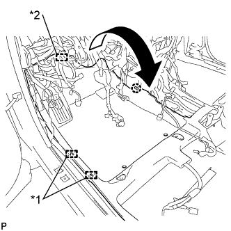
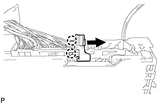
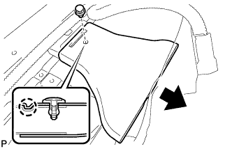
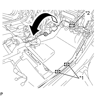
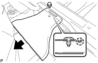
Disengage the 2 clamps and fastener.
-
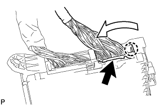
Disengage the claw and turn back the floor carpet as shown in the illustration.
Table 4. Text in Illustration *1 Clamp *2 Fastener -
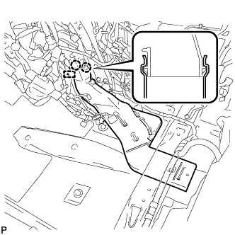
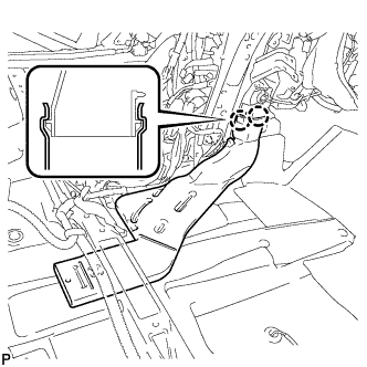
Remove the clip.
-
Disengage the claw and remove the rear No. 2 air duct.
-
- Click here
REMOVE REAR NO. 1 AIR DUCT
-
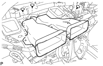
Disengage the clamp.
-
Disengage the 2 claws and remove the rear No. 1 air duct.
-
- Click here
REMOVE FRONT FLOOR CAUTION PLATE COVER
-
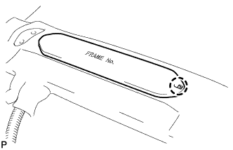
Disengage the claw.
-
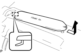
Disengage the guide and remove the frame number cover as shown in the illustration.
-
- Click here
REMOVE REAR NO. 4 AIR DUCT
-
Disengage the 2 clamps and fastener.
-
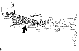
Disengage the claw and turn back the floor carpet as shown in the illustration.
Table 5. Text in Illustration *1 Clamp *2 Fastener -
Remove the clip.
-
Disengage the claw and remove the rear No. 4 air duct.
-
- Click here
REMOVE REAR NO. 3 AIR DUCT
-
Disengage the 2 claws and remove the rear No. 3 air duct.
-
- Click here
REMOVE CENTER HEATER TO REGISTER SUB DUCT
-
Remove the 3 clips and center heater to register sub duct.
-
- Click here
REMOVE NO. 5 INSTRUMENT PANEL BRACKET
-
Remove the 2 No. 5 instrument panel brackets.
-
- Click here
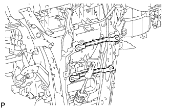
REMOVE NO. 1 INSTRUMENT PANEL BRACE SUB-ASSEMBLY
-
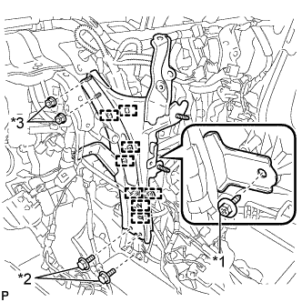
Disengage each clamp.
-
Remove the screw.
-
Remove the 2 bolts, 2 nuts and No. 1 instrument panel brace sub-assembly.
Table 6. Text in Illustration *1 Screw *2 Bolt *3 Nut
-
- Click here
REMOVE NO. 2 INSTRUMENT PANEL BRACE SUB-ASSEMBLY
-
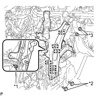
Disengage each clamp.
-
Remove the screw.
-
Remove the 2 bolts, 2 nuts and No. 2 instrument panel brace sub-assembly.
Table 7. Text in Illustration *1 Screw *2 Bolt *3 Nut
-
- Click here
REMOVE INSTRUMENT PANEL REINFORCEMENT ASSEMBLY WITH AIR CONDITIONING UNIT ASSEMBLY
-
Disengage each clamp.
-
Disconnect each connector.
-
Remove the bolt and disconnect the earth wire.
Table 8. Text in Illustration *1 Bolt *2 Earth Wire -
Disengage each clamp.
-
Disconnect the connector.
-
Disconnect the blower motor connector.
-
Disconnect the 2 air conditioning ECU connectors.
-
Remove the bolt and disconnect the earth wire.
-
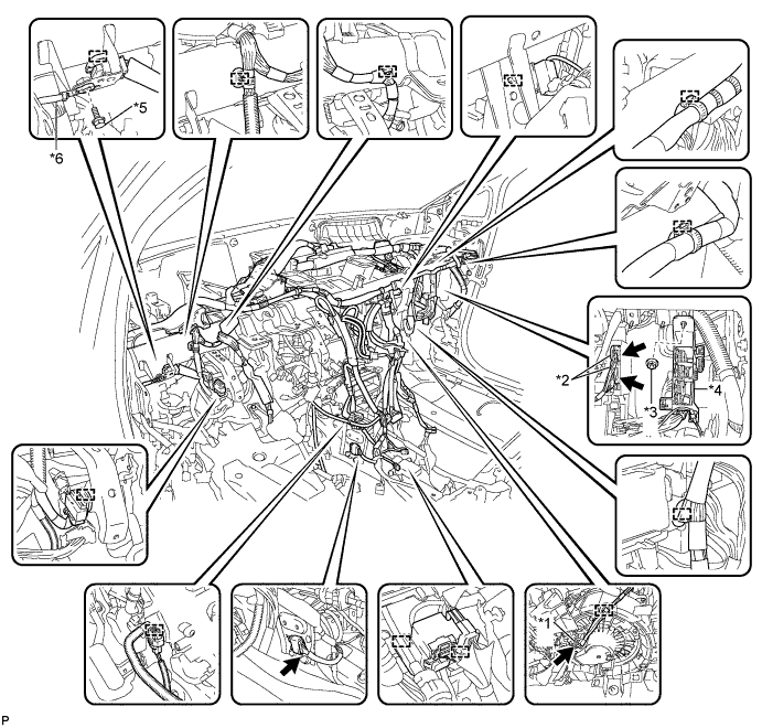
Remove the nut and disconnect the connector holder.
Table 9. Text in Illustration *1 Blower Motor Connector *2 Air Conditioning ECU Connector *3 Nut *4 Connector Holder *5 Bolt *6 Earth Wire -
Remove the 2 bolts and 2 caps from the engine compartment side.
-
Remove the nut.
-
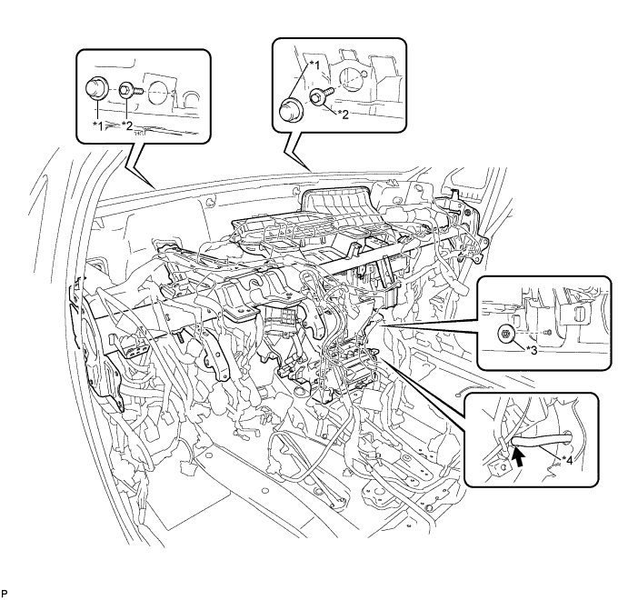
Disconnect the cooler drain hose.
Table 10. Text in Illustration *1 Cap *2 Bolt *3 Nut *4 Cooler Drain Hose -
Remove the 5 instrument panel safety pad caps.
-
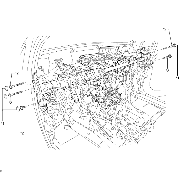
Using a "TORX" socket wrench (T40), remove the 5 "TORX" bolts and the instrument panel reinforcement assembly with air conditioning unit assembly.
Table 11. Text in Illustration *1 Instrument Panel Safety Pad Cap *2 "TORX" Bolt
-
- Click here
REMOVE NO. 1 AIR DUCT SUB-ASSEMBLY
-
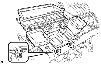
Disengage the 4 claws and remove the No. 1 air duct sub-assembly.
-
- Click here
REMOVE AIR CONDITIONING UNIT ASSEMBLY
-
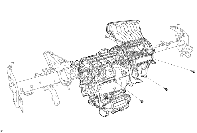
Remove the 3 bolts and air conditioning unit assembly from the instrument panel reinforcement assembly.
-