CENTER AIRBAG SENSOR ASSEMBLY INSTALLATION

-
INSTALL CENTER AIRBAG SENSOR ASSEMBLY
-
Check that the power switch is off.
-
Check that the cable is disconnected from the negative (-) auxiliary battery terminal.
CAUTION:
Wait at least 90 seconds after disconnecting the cable from the negative (-) auxiliary battery terminal to disable the SRS system.
-
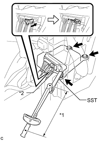
Text in Illustration *1 Fulcrum Length *2 Waterproof Sheet Using SST and a torque wrench, install the center airbag sensor assembly with the 3 bolts.
- SST
- 09961-00950
- Torque:
- without SST
- 18 N*m { 178 kgf*cm, 13 ft.*lbf }
- with SST
- 11 N*m { 112 kgf*cm, 8 ft.*lbf }
Note
-
Use a torque wrench with a fulcrum length of 250 mm (9.84 in.).
-
This torque value is effective when SST is parallel to a torque wrench.
-
If the center airbag sensor assembly has been dropped, or there are any cracks, dents or other defects in the case or connector, replace it with a new one.
-
When installing the center airbag sensor assembly, be careful that the SRS wiring does not interfere with or is not pinched between other parts.
-
When the power switch is first turned on (IG) after the center airbag sensor assembly has been replaced, make sure that no one is in the vehicle.
-
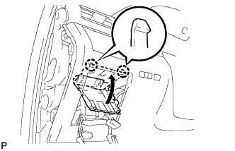
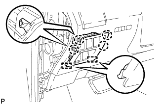
Connect the connector to the center airbag sensor assembly as shown in the illustration.
Note
When connecting any airbag connector, take care not to damage the airbag wire harness.
-
Check that the waterproof sheet is properly set.
-
Check that there is no looseness in the installation parts of the center airbag sensor assembly.
-
-
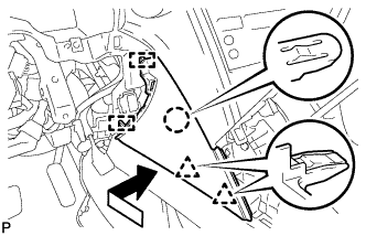
INSTALL CONSOLE BOX (for LHD)
-
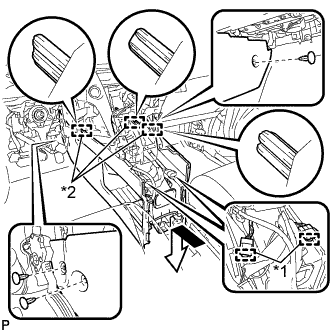
Text in Illustration *1 Clamp *2 Guide Engage the 3 guides as shown in the illustration.
-
Engage the 2 clamps.
-
Install the 3 clips.
-
Install the console box with the 5 screws <D>.
-
-
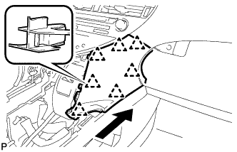
INSTALL CONSOLE BOX (for RHD)
-
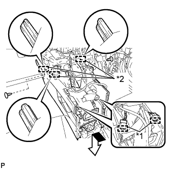
Text in Illustration *1 Clamp *2 Guide Engage the 3 guides as shown in the illustration.
-
Engage the 2 clamps.
-
Install the 2 clips.
-
Install the console box with the 5 screws <D>.
-
-
INSTALL FRONT CONSOLE BOX COVER
-
Connect the connector.
-
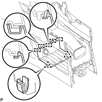
Engage the 5 guides and 2 clips, and install the front console box cover.
-
-
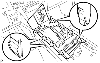
INSTALL REAR CONSOLE BOX ASSEMBLY
-
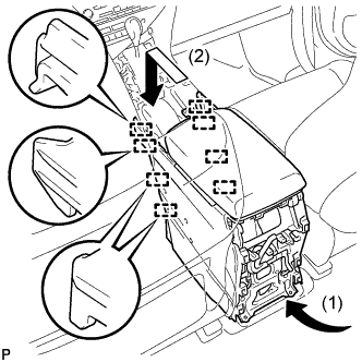
Engage the 8 guides as shown in the illustration.
Note
Make sure to install the rear console box assembly in the direction indicated by the arrow (1). Failure to do so will damage the console box and front seat.
-
Install the rear console box assembly with the 2 screws and 4 bolts.
-
-
INSTALL CONSOLE REAR END PANEL SUB-ASSEMBLY
-
w/o Rear Seat Entertainment System:
-
Engage the 5 claws and 6 clips to install the console rear end panel sub-assembly.
-
-
w/ Rear Seat Entertainment System:
-
Connect each connector.
-
Engage the 5 claws and 6 clips to install the console rear end panel sub-assembly.
-
-
-
INSTALL LOWER INSTRUMENT PANEL FINISH PANEL
-
Engage the 7 clips to install the lower instrument panel finish panel as shown in the illustration.
-
-
INSTALL INSTRUMENT PANEL FINISH PANEL
-
Engage the 2 guides, claw and 2 clips to install the instrument panel finish panel as shown in the illustration.
-
-
INSTALL LOWER INSTRUMENT PANEL FINISH PANEL SUB-ASSEMBLY
-
Connect each connector.
-
Engage the 8 clips and 2 guides.
-
Install the lower instrument panel finish panel sub-assembly with the 2 screws <D>.
-
Engage the 2 claws to close the cover as shown in the illustration.
-
-
INSTALL NO. 1 SWITCH HOLE BASE
-
Connect each connector.
-
Engage the 4 claws and 2 guides to install the No. 1 switch hole base.
-
-
INSTALL INSTRUMENT PANEL GARNISH LH
-
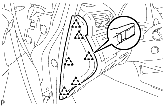
Engage the 6 clips to install the instrument panel garnish LH.
-
-
INSTALL NO. 2 CONSOLE BOX DUCT
-
Install the No. 2 console box duct with the 2 screws.
-
Connect each connector and engage the 2 clamps.
-
-
INSTALL UPPER CONSOLE PANEL SUB-ASSEMBLY
-
Engage the clamp.
-
Connect each connector.
-

Engage the 3 claws and 3 clips.
-
w/o Seat Heater System:
-
Connect the connector to the console box hole cover.
-
-
w/ Seat Heater System:
-
Connect the connector.
-
Engage the 6 claws to install the seat heater switch with console box hole cover.
-
-
Engage the 4 claws and 4 clips to install the upper console panel sub-assembly.
-
-
INSTALL SHIFT LEVER KNOB SUB-ASSEMBLY
-
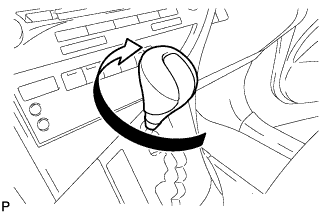
Turn the shift lever knob sub-assembly clockwise to install the shift lever knob sub-assembly.
-
-
CONNECT CABLE TO NEGATIVE AUXILIARY BATTERY TERMINAL
Note
When disconnecting the cable, some systems need to be initialized after the cable is reconnected Click here.
-
INSTALL REAR DECK FLOOR BOX
-
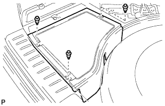
Install the rear deck floor box with the 3 clips.
-
-
PERFORM DIAGNOSTIC SYSTEM CHECK
-
Perform a diagnostic system check Click here.
-
-
INSPECT SRS WARNING LIGHT
-
Inspect the SRS warning light Click here.
-
-
INSPECT SUSPENSION CONTROL SYSTEM (w/ Air Suspension)
-
Inspect the suspension control system Click here.
-