LIGHTING SYSTEM Interior Light Power Source Circuit
DESCRIPTION
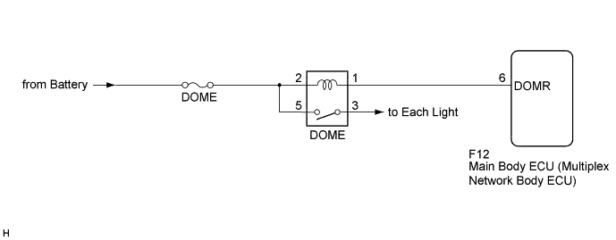
The main body ECU (multiplex network body ECU) controls operation of the DOME relay in order to supply power to the interior lights.
WIRING DIAGRAM
INSPECTION PROCEDURE
Note
Inspect the fuses for circuits related to this system before performing the following inspection procedure.
PROCEDURE
-
INSPECT DOME RELAY
-
Remove the DOME relay from the No. 1 relay block assembly.
-
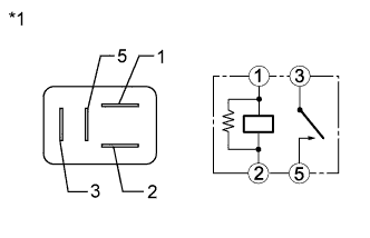
Text in Illustration *1 Component without harness connected
(DOME Relay)
Measure the resistance according to the value(s) in the table below.
Standard Resistance Tester Connection Condition Specified Condition 3 - 5 Voltage is not applied between terminals 1 and 2 10 kΩ or higher 3 - 5 Voltage is applied between terminals 1 and 2 Below 1 Ω
NG 
REPLACE DOME RELAY
OK 
-
-
CHECK HARNESS AND CONNECTOR (BATTERY - DOME RELAY)
-
Measure the voltage according to the value(s) in the table below.
Standard Voltage Tester Connection Condition Specified Condition Relay Terminal 2 - Body ground Power switch off 11 to 14 V Relay Terminal 5 - Body ground Power switch off 11 to 14 V
NG
REPAIR OR REPLACE HARNESS OR CONNECTOR
OK
-
-
CHECK HARNESS AND CONNECTOR (DOME RELAY - MAIN BODY ECU (MULTIPLEX NETWORK BODY ECU))
-
Disconnect the F12 main body ECU (multiplex network body ECU) connector.
-
Measure the resistance according to the value(s) in the table below.
Standard Resistance Tester Connection Condition Specified Condition Relay Terminal 1 - F12-6 (DOMR) Always Below 1 Ω Relay Terminal 1 - Body ground Always 10 kΩ or higher
NG
REPAIR OR REPLACE HARNESS OR CONNECTOR
OK
-
-
CHECK MAIN BODY ECU (MULTIPLEX NETWORK BODY ECU)
-
Install the DOME relay to the No. 1 relay block assembly.
-
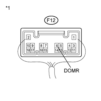
Text in Illustration *1 Component with harness connected
(Main Body ECU (Multiplex Network Body ECU))
Reconnect the F12 main body ECU (multiplex network body ECU) connector.
-
Measure the voltage according to the value(s) in the table below.
Standard Voltage Tester Connection Condition Specified Condition F12-6 (DOMR) - Body ground Power switch on (IG) Below 1 V
NG
PROCEED TO NEXT SUSPECTED AREA SHOWN IN PROBLEM SYMPTOMS TABLE Click here
OK 
REPAIR OR REPLACE HARNESS OR CONNECTOR (DOME RELAY - EACH LIGHT)
-