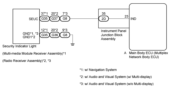
THEFT DETERRENT SYSTEM (w/ Intrusion Sensor) Security Indicator Light Circuit
DESCRIPTION
Even when the theft deterrent system is in the disarmed state, the security indicator blinks due to a signal output from the immobiliser system. The security indicator blinks continuously due to a continuous signal received from the immobiliser system while in the armed state.
The main body ECU (multiplex network body ECU) causes the security indicator to come on only during the arming preparation and alarm sounding states.
WIRING DIAGRAM
INSPECTION PROCEDURE
PROCEDURE
-
PERFORM ACTIVE TEST USING INTELLIGENT TESTER
-
Connect the intelligent tester to the DLC3.
-
Turn the power switch on (IG).
-
Turn the intelligent tester on.
-
Select the item below in the Active Test and then check that the indicator operates.
Main Body Tester Display Test Part Control Range Diagnostic Note Security Indicator Security indicator ON / OFF - OK The security indicator light flashes and goes off correctly when operated through the intelligent tester.
NG 
INSPECT INSTRUMENT PANEL JUNCTION BLOCK ASSEMBLY Click here
OK 
PROCEED TO NEXT SUSPECTED AREA SHOWN IN PROBLEM SYMPTOMS TABLE Click here
-
-
INSPECT INSTRUMENT PANEL JUNCTION BLOCK ASSEMBLY
-
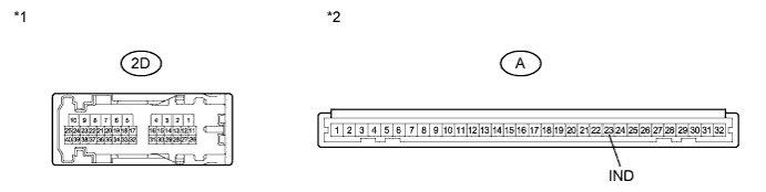
Disconnect the 2D instrument panel junction block assembly and A main body ECU (multiplex network body ECU) connectors.
-
Measure the resistance according to the value(s) in the table below.
Standard Resistance Tester Connection Condition Specified Condition 2D-35 - A-23 (IND) Always Below 1 Ω Text in Illustration *1 Component without harness connected
(Instrument Panel Junction Block Assembly)
*2 Front view of wire harness connector
(to Main Body ECU (Multiplex Network Body ECU))
NG 
REPLACE INSTRUMENT PANEL JUNCTION BLOCK ASSEMBLY
OK 
-
-
CHECK HARNESS AND CONNECTOR (SECURITY INDICATOR LIGHT - MAIN BODY ECU)
-
Reconnect the 2D instrument panel junction block assembly connector.
-
Measure the resistance according to the value(s) in the table below.
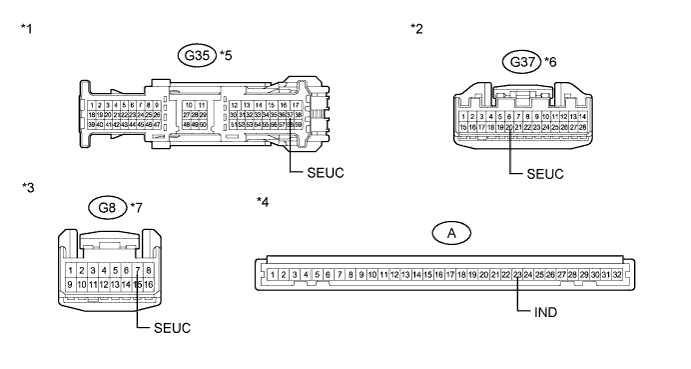
Standard Resistance Tester Connection Condition Specified Condition G35-37 (SEUC) - A-23 (IND)*1 Always Below 1 Ω G35-37 (SEUC) - Body ground*1 Always 10 kΩ or higher G37-20 (SEUC) - A-23 (IND)*2 Always Below 1 Ω G37-20 (SEUC) - Body ground*2 Always 10 kΩ or higher G8-7 (SEUC) - A-23 (IND)*3 Always Below 1 Ω G8-7 (SEUC) - Body ground*3 Always 10 kΩ or higher
-
*1: w/ Navigation System
-
*2: w/ Audio and Visual System (w/ Multi-display)
-
*3: w/ Audio and Visual System (w/o Multi-display)
Text in Illustration *1 Front view of wire harness connector
(to Multi-media Module Receiver Assembly)
*2 Front view of wire harness connector
(to Radio Receiver Assembly)
*3 Front view of wire harness connector
(to Radio Receiver Assembly)
*4 Front view of wire harness connector
(to Main Body ECU (Multiplex Network Body ECU))
*5 w/ Navigation System *6 w/ Audio and Visual System (w/ Multi-display) *7 w/ Audio and Visual System (w/o Multi-display) - - -
NG
REPAIR OR REPLACE HARNESS OR CONNECTOR
OK
-
-
CHECK HARNESS AND CONNECTOR (SECURITY INDICATOR LIGHT - BODY GROUND)
-
Measure the resistance according to the value(s) in the table below.
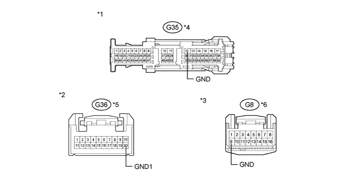
Standard Resistance Tester Connection Condition Specified Condition G35-12 (GND) - Body ground*1 Always Below 1 Ω G36-20 (GND1) - Body ground*2 Always Below 1 Ω G8-9 (GND) - Body ground*3 Always Below 1 Ω
-
*1: w/ Navigation System
-
*2: w/ Audio and Visual System (w/ Multi-display)
-
*3: w/ Audio and Visual System (w/o Multi-display)
Text in Illustration *1 Front view of wire harness connector
(to Multi-media Module Receiver Assembly)
*2 Front view of wire harness connector
(to Radio Receiver Assembly)
*3 Front view of wire harness connector
(to Radio Receiver Assembly)
*4 w/ Navigation System *5 w/ Audio and Visual System (w/ Multi-display) *6 w/ Audio and Visual System (w/o Multi-display) Result Result Proceed to OK (w/ Navigation System) A OK (w/ Audio and Visual System (w/ Multi-display)) B OK (w/ Audio and Visual System (w/o Multi-display)) C NG D -
B
INSPECT RADIO RECEIVER ASSEMBLY (SECURITY INDICATOR LIGHT) Click here
C
INSPECT RADIO RECEIVER ASSEMBLY (SECURITY INDICATOR LIGHT) Click here
D
REPAIR OR REPLACE HARNESS OR CONNECTOR
A
-
-
INSPECT MULTI-MEDIA MODULE RECEIVER ASSEMBLY (SECURITY INDICATOR LIGHT)
-
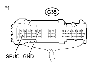
Text in Illustration *1 Component with harness connected
(Multi-media Module Receiver Assembly (Security Indicator Light))
Reconnect the G35 multi-media module receiver assembly connector with the A main body ECU connector still disconnected.
-
Apply battery voltage from the wire harness back side between the specified terminals of the indicator, and check the lighting condition of the security indicator.
Standard Measurement Condition Specified Condition Battery positive (+) → Terminal G35-37 (SEUC)
Battery negative (-) → Terminal G35-12 (GND)
Security indicator comes on Note
-
If the positive (+) lead and the negative (-) lead are incorrectly connected, the security indicator will not come on.
-
Voltage of more than 12 V will damage the security indicator.
-
If the voltage is too low, the security indicator will not come on.
-
NG
REPLACE MULTI-MEDIA MODULE RECEIVER ASSEMBLY Click here
OK
REPLACE MAIN BODY ECU (MULTIPLEX NETWORK BODY ECU) Click here
-
-
INSPECT RADIO RECEIVER ASSEMBLY (SECURITY INDICATOR LIGHT)
-
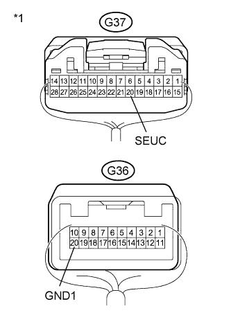
Text in Illustration *1 Component with harness connected
(Radio Receiver Assembly (Security Indicator Light))
Reconnect the G36 and G37 radio receiver assembly connector with the A main body ECU connector still disconnected.
-
Apply battery voltage from the wire harness back side between the specified terminals of the indicator, and check the lighting condition of the security indicator.
Standard Measurement Condition Specified Condition Battery positive (+) → Terminal G37-20 (SEUC)
Battery negative (-) → Terminal G36-20 (GND1)
Security indicator comes on Note
-
If the positive (+) lead and the negative (-) lead are incorrectly connected, the security indicator will not come on.
-
Voltage of more than 12 V will damage the security indicator.
-
If the voltage is too low, the security indicator will not come on.
-
NG
REPLACE RADIO RECEIVER ASSEMBLY Click here
OK
REPLACE MAIN BODY ECU (MULTIPLEX NETWORK BODY ECU) Click here
-
-
INSPECT RADIO RECEIVER ASSEMBLY (SECURITY INDICATOR LIGHT)
-
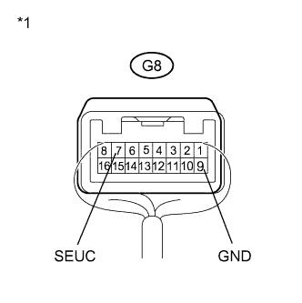
Text in Illustration *1 Component with harness connected
(Radio Receiver Assembly (Security Indicator Light))
Reconnect the G8 radio receiver assembly connector with the A main body ECU connector still disconnected.
-
Apply battery voltage from the wire harness back side between the specified terminals of the indicator, and check the lighting condition of the security indicator.
Standard Measurement Condition Specified Condition Battery positive (+) → Terminal G8-7 (SEUC)
Battery negative (-) → Terminal G8-9 (GND)
Security indicator comes on Note
-
If the positive (+) lead and the negative (-) lead are incorrectly connected, the security indicator will not come on.
-
Voltage of more than 12 V will damage the security indicator.
-
If the voltage is too low, the security indicator will not come on.
-
NG
REPLACE RADIO RECEIVER ASSEMBLY (SECURITY INDICATOR LIGHT) Click here
OK
REPLACE MAIN BODY ECU (MULTIPLEX NETWORK BODY ECU) Click here
-