ENTRY AND START SYSTEM (for Start Function) Power Source Mode does not Change to ON (READY)
DESCRIPTION
When the electronic key is in the cabin and the power switch is pressed, the power management control ECU receives a signal and changes the power source mode. In addition, when the power switch is pressed with the shift lever in P and the brake pedal depressed, the hybrid system turns on (READY).
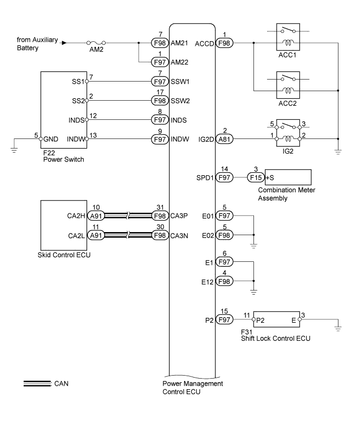
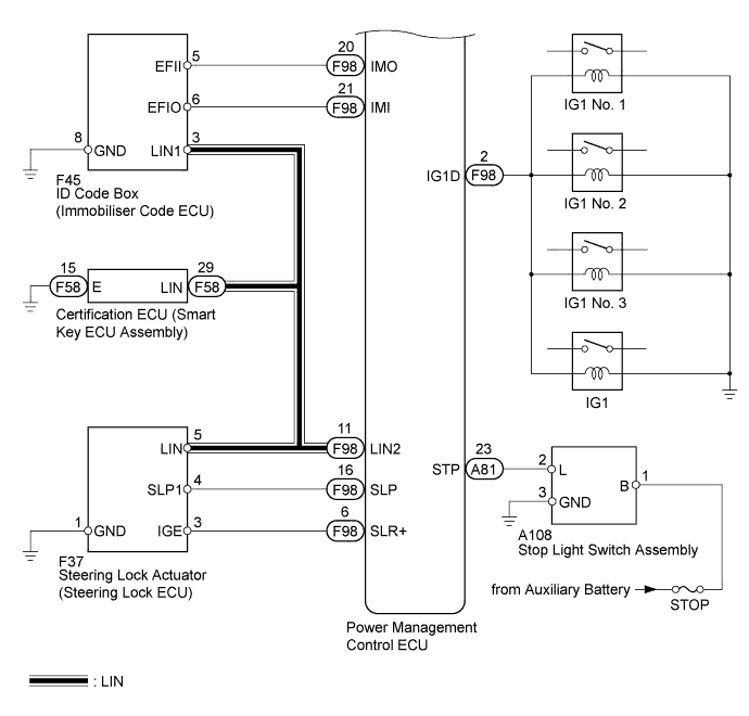
WIRING DIAGRAM
INSPECTION PROCEDURE
Note
-
When the power management control ECU is replaced with a new one and the cable from the negative (-) auxiliary battery terminal is connected, the power source mode becomes on (IG) mode. When the auxiliary battery is removed and reinstalled, the power source mode that was selected when the auxiliary battery was removed is restored.
-
Inspect the fuses for circuits related to this system before performing the following inspection procedure.
PROCEDURE
-
CHECK HYBRID SYSTEM READY ON
-
Place the electrical key on the driver seat.
-
Move the shift lever to P.
-
Depress the brake pedal.
-
Check that the power switch indicator light is green. Then press the power switch to check if the hybrid system turns on (READY).
OK Power source mode becomes on (READY).
NG 
CHECK FOR DTC Click here
OK 
END (HYBRID SYSTEM PERMISSION CONDITIONS WERE NOT SATISFIED)
-
-
CHECK FOR DTC
-
Turn the power switch off.
-
Connect the intelligent tester to the DLC3.
-
Turn the power switch on (IG).
-
Turn the intelligent tester on.
-
Enter the following menus: Powertrain / Hybrid Control / DTC.
-
Check for DTCs.
OK DTC is not output.
NG 
GO TO HYBRID CONTROL SYSTEM (DIAGNOSTIC TROUBLE CODE CHART) Click here
OK 
-
-
CHECK FOR DTC
-
Enter the following menus: Body / Power Source Control / Data List.
-
Check for DTCs.
OK DTC is not output.
NG
GO TO DIAGNOSTIC TROUBLE CODE CHART Click here
OK
-
-
CHECK POWER SOURCE CONDITION
-
Check if the power source mode changes.
-
When the key is inside the vehicle and the shift lever is in P, check that the power source mode changes.
Result Result Proceed to off → on (ACC) → on (IG) → off A Power source mode does not change to on (IG and ACC) B Power source mode does not change to on (IG) C Power source mode does not change to on (ACC) D
-
B
GO TO OTHER FLOW CHART (Power Source Mode does not Change to ON (IG and ACC)) Click here
C
GO TO OTHER FLOW CHART (Power Source Mode does not Change to ON (IG)) Click here
D
GO TO OTHER FLOW CHART (Power Source Mode does not Change to ON (ACC)) Click here
A
-
-
READ VALUE USING INTELLIGENT TESTER (STEERING UNLOCK SWITCH)
-
Enter the following menus: Body / Power Source Control / Date List.
-
Read the Data List according to the display on the intelligent tester.
Power Source Control Tester Display Measurement Item/Range Normal Condition Diagnostic Note Steering Unlock Switch Steering unlock condition/ON or OFF ON: Steering unlocked
OFF: Steering locked
- OK ON (steering is unlocked) and OFF (steering is locked) appear on the screen.
NG
GO TO STEERING LOCK SYSTEM Click here
OK
-
-
READ VALUE USING INTELLIGENT TESTER (STOP LIGHT SWITCH ASSEMBLY)
-
Read the Data List according to the display on the intelligent tester.
Power Source Control Tester Display Measurement Item/Range Normal Condition Diagnostic Note Stop Light Switch1 Stop light switch 1/ON or OFF ON: Brake pedal depressed
OFF: Brake pedal released
- OK ON (brake pedal is depressed) and OFF (brake pedal is released) appear on the screen.
NG
CHECK HARNESS AND CONNECTOR (STOP LIGHT SWITCH ASSEMBLY - POWER SOURCE AND BODY GROUND) Click here
OK
-
-
READ VALUE USING INTELLIGENT TESTER (L CODE)
-
Enter the following menus: Body / Entry & Start / Data List.
-
Read the Data List according to the display on the intelligent tester.
Entry & Start Tester Display Measurement Item/Range Normal Condition Diagnostic Note L Code Check L code certification result/OK or NG OK: L code certification result normal
NG: L code certification result abnormal
- OK OK appears on the screen.
NG
REPLACE STEERING LOCK ACTUATOR ASSEMBLY (STEERING LOCK ECU) Click here
OK
-
-
READ VALUE USING INTELLIGENT TESTER (ENGINE START REQUEST)
-
Read the Data List according to the display on the intelligent tester.
Entry & Start Tester Display Measurement Item/Range Normal Condition Diagnostic Note Engine Start Request Start request signal response/OK or NG OK: Start request condition signal received
NG: Start request condition signal not received
- OK OK appears on the screen.
NG
REPLACE CERTIFICATION ECU (SMART KEY ECU ASSEMBLY)
OK
-
-
READ VALUE USING INTELLIGENT TESTER (S CODE)
-
Read the Data List according to the display on the intelligent tester.
Entry & Start Tester Display Measurement Item/Range Normal Condition Diagnostic Note S Code Check S code certification result/OK or NG OK: S code certification result normal
NG: S code certification result abnormal
- OK OK appears on the screen.
NG
REPLACE CERTIFICATION ECU (SMART KEY ECU ASSEMBLY) Click here
OK
-
-
CHECK ID CODE BOX (IMMOBILISER CODE ECU)
-
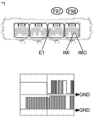
Text in Illustration *1 Component with harness connected
(Power Management Control ECU)
Measure the voltage according to the value(s) in the table below.
Tester Connection CH1: F98-20 (IMO) - F97-6 (E1)
CH2: F98-21 (IMI) - F97-6 (E1)
Tool Setting 5 V/DIV., 200 ms/DIV Idling with warm engine off → on (IG) → on (READY) OK The waveform is displayed as shown in illustration.
NG
REPLACE ID CODE BOX (IMMOBILISER CODE ECU)
OK
-
-
READ VALUE USING INTELLIGENT TESTER
-
Enter the following menus: Body / Power Source Control / Data List.
-
Read the Data List according to the display on the intelligent tester.
Power Source Control Tester Display Measurement Item/Range Normal Condition Diagnostic Note Starter Request Signal Hybrid control system start request signal / ON or OFF ON: STSW signal is ON
OFF: STSW signal is OFF
- -
Proceed to the next step based on inspection result.
Result Result Proceed to Data List display changes when the power switch is operated. A Data List display does not change even when the power switch is operated. (for LHD) B Data List display does not change even when the power switch is operated. (for RHD) C
B
REPLACE POWER MANAGEMENT CONTROL ECU (for LHD) Click here
C
REPLACE POWER MANAGEMENT CONTROL ECU (for RHD) Click here
A
GO TO HYBRID CONTROL SYSTEM Click here
-
-
CHECK HARNESS AND CONNECTOR (STOP LIGHT SWITCH ASSEMBLY - POWER SOURCE AND BODY GROUND)
-
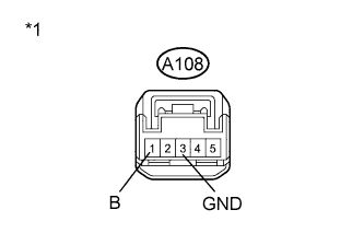
Text in Illustration *1 Front view of wire harness connector
(to Stop Light Switch Assembly)
Disconnect the A108 connector from the stop light switch assembly.
-
Measure the voltage and resistance according to the value(s) in the table below.
Standard Voltage Tester Connection Condition Specified Condition A108-1 (B) - A108-3 (GND) Always 11 to 14 V Standard Resistance Tester Connection Condition Specified Condition A108-3 (GND) - Body ground Always Below 1 Ω
NG
REPAIR OR REPLACE HARNESS OR CONNECTOR
OK
-
-
CHECK STOP LIGHT SWITCH ASSEMBLY
-
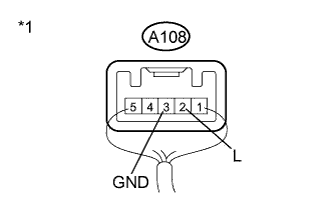
Text in Illustration *1 Component with harness connected
(Stop Light Switch Assembly)
Reconnect the A108 connector to the stop light switch assembly.
-
Measure the voltage according to the value(s) in the table below.
Standard Voltage Tester Connection Condition Specified Condition A108-2 (L) - A108-3 (GND) Power switch off, brake pedal not depressed Below 1 V A108-2 (L) - A108-3 (GND) Power switch off, brake pedal depressed 11 to 14 V
NG
REPLACE STOP LIGHT SWITCH ASSEMBLY Click here
OK
-
-
CHECK HARNESS AND CONNECTOR (STOP LIGHT SWITCH ASSEMBLY - POWER MANAGEMENT CONTROL ECU)
-
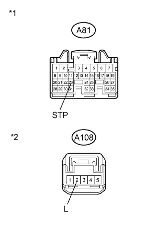
Text in Illustration *1 Front view of wire harness connector
(to Power Management Control ECU)
*2 Front view of wire harness connector
(to Stop Light Switch Assembly)
Disconnect the A81 connector from the power management control ECU.
-
Measure the resistance according to the value(s) in the table below.
Standard Resistance Tester Connection Condition Specified Condition A81-23 (STP) - A108-2 (L) Always Below 1 Ω A81-23 (STP) - Body ground Always 10 kΩ or higher
NG
REPAIR OR REPLACE HARNESS OR CONNECTOR
OK
REPLACE POWER MANAGEMENT CONTROL ECU
-
-
REPLACE STEERING LOCK ACTUATOR ASSEMBLY (STEERING LOCK ECU)
-
Replace steering lock actuator Click here.
NEXT
-
-
CHECK HYBRID SYSTEM READY ON
-
Place the electrical key on the driver seat.
-
Move the shift lever to P.
-
Depress the brake pedal.
-
Check that the power switch indicator light is green. Then press the power switch to check if the hybrid system turns on (READY).
OK Power source mode becomes on (READY).
NG
REPLACE ID CODE BOX (IMMOBILISER CODE ECU)
OK
END (STEERING LOCK ACTUATOR (STEERING LOCK ECU) WAS DEFECTIVE)
-
-
REPLACE CERTIFICATION ECU (SMART KEY ECU ASSEMBLY)
-
Replace certification ECU (smart key ECU assembly).
NEXT
-
-
CHECK HYBRID SYSTEM READY ON
-
Place the electrical key on the driver seat.
-
Move the shift lever to P.
-
Depress the brake pedal.
-
Check that the power switch indicator light is green. Then press the power switch to check if the hybrid system turns on (READY).
OK Power source mode becomes on (READY).
NG
REPLACE ID CODE BOX (IMMOBILISER CODE ECU)
OK
END (ID CODE BOX (IMMOBILISER CODE ECU) WAS DEFECTIVE)
-