- Click here
PRECAUTION (w/ Navigation System for HDD)
Note:After the power switch is turned off, the display and navigation module display (HDD navigation system) records various types of memory and settings. As a result, after turning the power switch off, make sure to wait for the time specified in the following table before disconnecting the cable from the negative (-) battery terminal.
Table 1. Waiting Time before Disconnecting Cable from Negative (-) Battery Terminal Specification Waiting Time w/o Telematics transceiver 60 sec. w/ Telematics transceiver 120 sec. - Click here
REMOVE REAR DECK FLOOR BOX
-
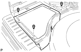
Remove the 3 clips and the rear deck floor box.
-
- Click here
DISCONNECT CABLE FROM NEGATIVE BATTERY TERMINAL
CAUTION:Wait at least 90 seconds after disconnecting the cable from the negative (-) battery terminal to disable the SRS system.
Note:When disconnecting the cable, some systems need to be initialized after the cable is reconnected (Click here).
- Click here
REMOVE REAR DOOR INSIDE HANDLE BEZEL PLUG
-
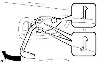
Using a moulding remover, disengage the 3 claws and remove the rear door inside handle bezel plug as shown in the illustration.
-
- Click here
REMOVE REAR POWER WINDOW REGULATOR SWITCH ASSEMBLY WITH REAR DOOR ARMREST BASE PANEL
-
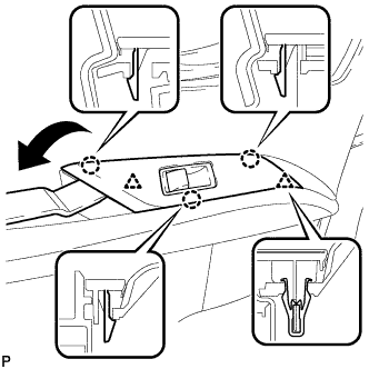
Using a moulding remover, disengage the 2 clips and 3 claws.
-
Disconnect the connector and remove the rear power window regulator switch assembly with rear door armrest base panel.
-
- Click here
REMOVE REAR DOOR ARMREST COVER
-
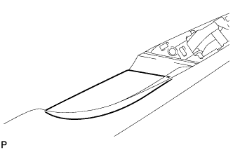
Remove the rear door armrest cover.
-
- Click here
REMOVE COURTESY LIGHT ASSEMBLY
-
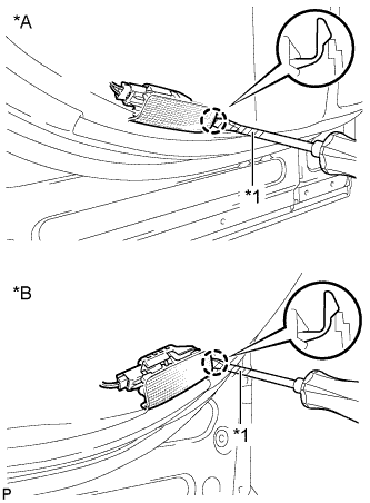
Using a screwdriver wrapped with protective tape, disengage the claw.
Table 2. Text in Illustration *A for LH Side *B for RH Side *1 Protective Tape -
Disconnect the connector and remove the courtesy light assembly.
-
- Click here
REMOVE REAR DOOR TRIM BOARD SUB-ASSEMBLY
-
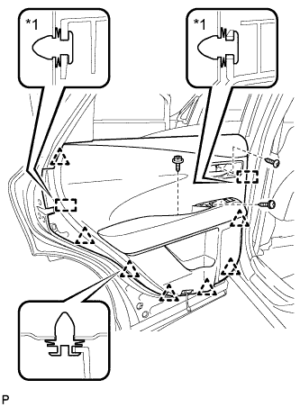
Remove the 3 screws.
-
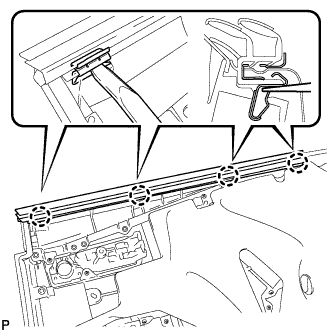
Using a clip remover, disengage the 7 clips and 2 rear door trim board retainers.
Table 3. Text in Illustration *1 Rear Door Trim Board Retainer -
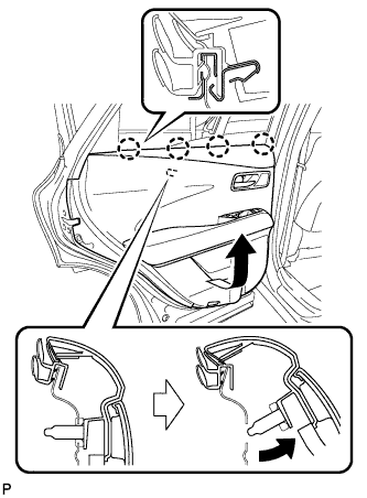
Pull out the rear door trim board sub-assembly in the direction indicated by the arrow as shown in the illustration.
-
Raise the rear door trim board sub-assembly to disengage the 4 claws and remove the rear door trim board sub-assembly together with the rear door inner glass weatherstrip.
-
for 12 Speakers or 15 Speakers:
-
Disconnect the connector.
-
-
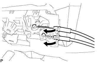
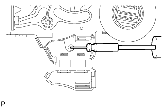
Disconnect the rear door lock remote control cable assembly and rear door inside locking cable assembly as shown in the illustration.
-
Remove the 2 rear door trim board retainers (green) from the rear door trim board sub-assembly.
-
- Click here
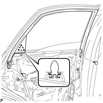
REMOVE REAR DOOR INNER GLASS WEATHERSTRIP
-
Using a moulding remover, disengage the 4 claws and remove the rear door inner glass weatherstrip from the rear door trim board sub-assembly as shown in the illustration.
-
- Click here
REMOVE REAR DOOR FRAME GARNISH
-
Remove the 2 clips.
-
Disengage the clip and remove the rear door frame garnish.
-
- Click here
REMOVE REAR DOOR TRIM BRACKET
-
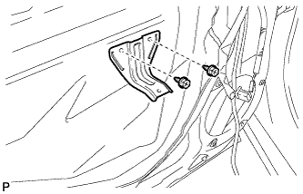
Remove the 2 screws and rear door trim bracket.
-
- Click here
REMOVE REAR DOOR SERVICE HOLE COVER
-
Disconnect the 2 connectors and remove the rear door service hole cover.
Tip:Remove any remaining butyl tape from the door.
-
- Click here
REMOVE REAR DOOR GLASS RUN
-
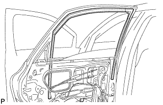
Remove the rear door glass run.
-
- Click here
REMOVE REAR DOOR WINDOW REAR GUIDE SUB-ASSEMBLY
-
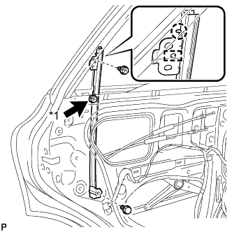
Loosen the temporary screw.
Table 4. Text in Illustration *1 Temporary Screw -
Remove the bolt and screw.
-
Disengage the claw, guide and remove the rear door window rear guide sub-assembly.
-
Remove the temporary screw from the rear door window rear guide sub-assembly.
-
- Click here
REMOVE REAR DOOR REAR GUIDE SEAL
-
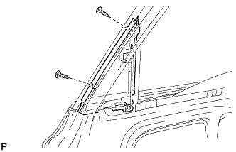
Remove the 2 screws and rear door rear guide seal.
-
- Click here
REMOVE REAR DOOR GLASS SUB-ASSEMBLY
-
Connect the cable to the negative (-) battery terminal and the rear power window regulator motor connector.
-
Connect the power window regulator switch assembly and move the rear door glass sub-assembly so that the door glass bolts can be seen.
-
w/ Navigation System for HDD:
Note:After the power switch is turned off, the display and navigation module display (HDD navigation system) records various types of memory and settings. As a result, after turning the power switch off, make sure to wait for the time specified in the following table before disconnecting the cable from the negative (-) battery terminal.
Table 5. Waiting Time before Disconnecting Cable from Negative (-) Battery Terminal Specification Waiting Time w/o Telematics transceiver 60 sec. w/ Telematics transceiver 120 sec.
-
-
Disconnect the power window regulator switch assembly and rear power window regulator motor connector.
-
Disconnect the cable from the negative (-) battery terminal.
CAUTION:Wait for 90 seconds after disconnecting the terminal to prevent the airbag from deploying (Click here).
-
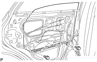
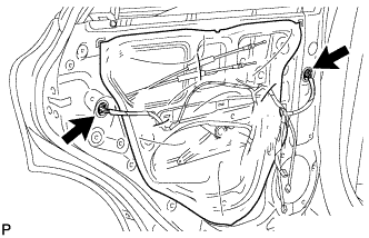
Remove the 2 bolts.
Note:After the bolts are removed, do not allow the door glass to fall.
-
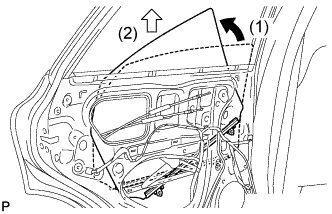
Remove the rear door glass sub-assembly as indicated by the arrows in the order shown in the illustration.
Note:Do not damage the door glass.
-
- Click here
REMOVE REAR DOOR LOCK ASSEMBLY (w/o Double Locking System)
-
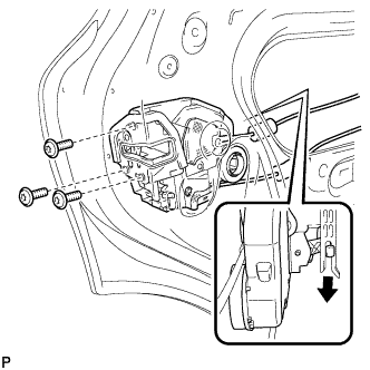
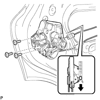
Using a T30 "TORX" socket wrench, remove the 3 screws.
-
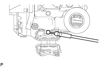
Move the rear door lock assembly downward and pull the release plate out of the rear door outside handle frame.
-
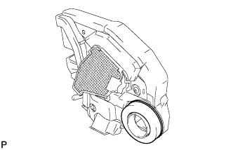
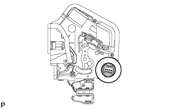
Remove the door lock wiring harness seal from the rear door lock assembly.
-
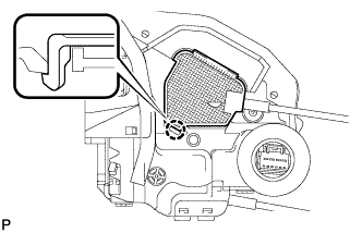
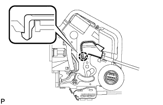
Using a screwdriver, disengage the claw.
Tip:Tape the screwdriver tip before use.
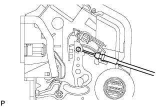
-
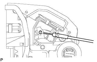
Remove the rear door lock remote control cable assembly.
-
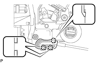
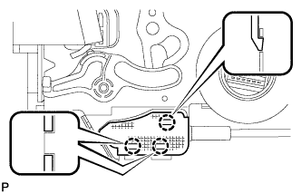
Using a screwdriver, disengage the 3 claws.
Tip:Tape the screwdriver tip before use.
-
Remove the rear door inside locking cable assembly.
-
- Click here
REMOVE REAR DOOR LOCK ASSEMBLY (w/ Double Locking System)
-
Using a T30 "TORX" socket wrench, remove the 3 screws.
-
Move the rear door lock assembly downward and pull the release plate out of the rear door outside handle frame.
-
Remove the door lock wiring harness seal from the rear door lock assembly.
-
Using a screwdriver, disengage the claw.
Tip:Tape the screwdriver tip before use.
-
Remove the rear door lock remote control cable assembly.
-
Using a screwdriver, disengage the 3 claws.
Tip:Tape the screwdriver tip before use.
-
Remove the rear door inside locking cable assembly.
-