FRONT DOOR LOCK REMOVAL

-
PRECAUTION (w/ Navigation System for HDD)
Note
After the power switch is turned off, the display and navigation module display (HDD navigation system) records various types of memory and settings. As a result, after turning the power switch off, make sure to wait for the time specified in the following table before disconnecting the cable from the negative (-) battery terminal.
Waiting Time before Disconnecting Cable from Negative (-) Battery Terminal Specification Waiting Time w/o Telematics transceiver 60 sec. w/ Telematics transceiver 120 sec. -
REMOVE REAR DECK FLOOR BOX
-
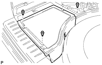
Remove the 3 clips and the rear deck floor box.
-
-
DISCONNECT CABLE FROM NEGATIVE BATTERY TERMINAL
CAUTION:
Wait at least 90 seconds after disconnecting the cable from the negative (-) battery terminal to disable the SRS system.
Note
When disconnecting the cable, some systems need to be initialized after the cable is reconnected Click here.
-
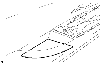
REMOVE FRONT DOOR INSIDE HANDLE BEZEL PLUG
-
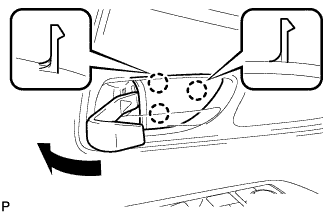
Using a moulding remover, disengage the 3 claws and remove the front door inside handle bezel plug as shown in the illustration.
-
-
REMOVE POWER WINDOW REGULATOR MASTER SWITCH ASSEMBLY WITH FRONT DOOR ARMREST BASE PANEL (for Driver Side)
-
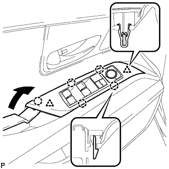
Using a moulding remover, disengage the 2 clips and 5 claws as shown in the illustration.
-
Disconnect the connector and remove the power window regulator master switch assembly with front door armrest base panel.
-
-
REMOVE POWER WINDOW REGULATOR SWITCH ASSEMBLY WITH FRONT DOOR ARMREST BASE PANEL (for Front Passenger Side)
-
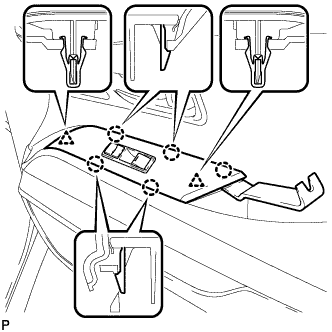
Using a moulding remover, disengage the 2 clips and 5 claws.
-
Disconnect the connector and remove the power window regulator switch assembly with front door armrest base panel.
-
-
REMOVE DOOR ARMREST COVER
-
Remove the door armrest cover.
-
-
REMOVE COURTESY LIGHT ASSEMBLY
-
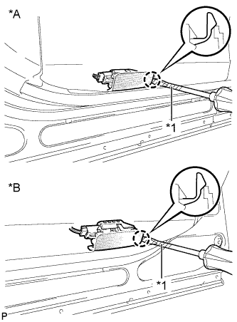
Text in Illustration *A for LH Side *B for RH Side *1 Protective Tape Using a screwdriver wrapped with protective tape, disengage the claw.
-
Disconnect the connector and remove the courtesy light assembly.
-
-
REMOVE NO. 1 FRONT DOOR STIFFENER CUSHION
-
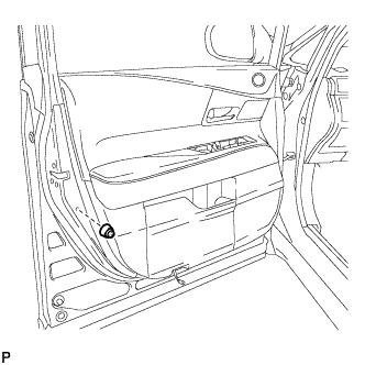
Remove the screw and No. 1 front door stiffener cushion.
-
-
REMOVE FRONT DOOR TRIM BOARD SUB-ASSEMBLY
-
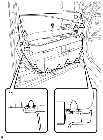
Remove the 3 screws.
-
Using a clip remover, disengage the 10 clips and front door trim board retainer.
Text in Illustration *1 Front Door Trim Board Retainer -
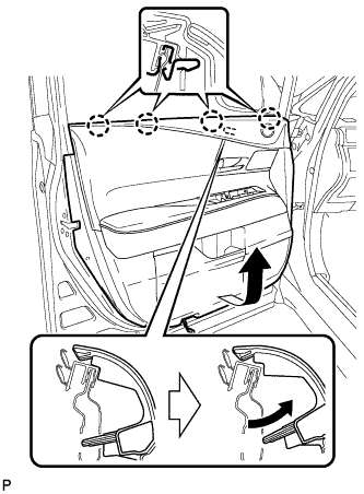
Pull out the front door trim board sub-assembly in the direction indicated by the arrow as shown in the illustration.
-
Raise the front door trim board sub-assembly to disengage the 4 claws and remove the front door trim board sub-assembly together with the front door inner glass weatherstrip.
-
Disconnect each connector.
-
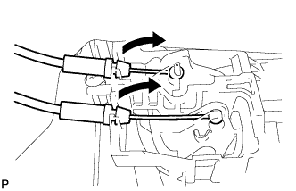
Disconnect the front door lock remote control cable assembly and front door inside locking cable assembly.
-
Remove the front door trim board retainer (green) from the front door trim board sub-assembly.
-
-
REMOVE FRONT DOOR INNER GLASS WEATHERSTRIP
-
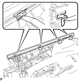
Using a moulding remover, disengage the 4 claws and remove the front door inner glass weatherstrip from the front door trim board sub-assembly as shown in the illustration.
-
-
REMOVE DOOR FRAME GARNISH
-
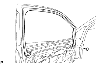
Remove the 2 clips and door frame garnish.
-
-
REMOVE FRONT NO. 3 SPEAKER ASSEMBLY
-
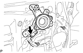
Disconnect the connector.
-
Remove the 2 screws.
-
Disengage the clip and remove the front No. 3 speaker assembly.
-
-
REMOVE OUTER MIRROR CONTROL ECU ASSEMBLY
-
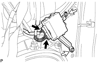
Disconnect each connector.
-
Remove the 2 screws and the outer mirror control ECU assembly.
-
-
REMOVE NO. 1 FRONT DOOR TRIM BRACKET
-
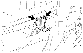
Remove the 2 screws and No. 1 front door trim bracket.
-
-
REMOVE FRONT DOOR SERVICE HOLE COVER
-
Disconnect the connector.
-
Remove the front door service hole cover.
Tech Tips
Remove any remaining butyl tape from the door.
-
-
REMOVE FRONT DOOR GLASS SUB-ASSEMBLY
-
Connect the cable to the negative (-) battery terminal.
-
Connect the power window regulator master switch assembly and move the front door glass sub-assembly so that the door glass bolts can be seen.
-
w/ Navigation System for HDD:
Note
After the power switch is turned off, the display and navigation module display (HDD navigation system) records various types of memory and settings. As a result, after turning the power switch off, make sure to wait for the time specified in the following table before disconnecting the cable from the negative (-) battery terminal.
Waiting Time before Disconnecting Cable from Negative (-) Battery Terminal Specification Waiting Time w/o Telematics transceiver 60 sec. w/ Telematics transceiver 120 sec.
-
-
Disconnect the cable from the negative (-) battery terminal and power window regulator master switch assembly.
CAUTION:
Wait at least 90 seconds after disconnecting the cable from the negative (-) battery terminal to disable the SRS system Click here.
-
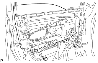
Remove the 2 bolts.
Note
After the bolts are removed, do not allow the door glass to fall.
-
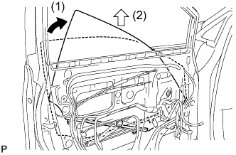
Remove the front door glass sub-assembly as indicated by the arrows in the order shown in the illustration.
Note
Do not damage the door glass.
-
-
REMOVE FRONT DOOR GLASS RUN
-
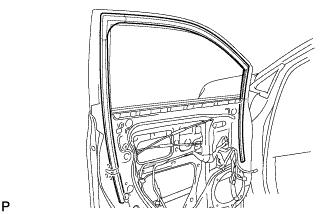
Remove the front door glass run.
-
-
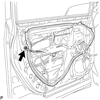
REMOVE FRONT DOOR REAR LOWER FRAME SUB-ASSEMBLY
-
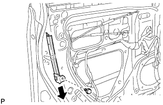
Remove the bolt and front door rear lower frame sub-assembly as shown in the illustration.
-
-
REMOVE FRONT DOOR OUTSIDE HANDLE COVER WITH LOCK CYLINDER ASSEMBLY (for Driver Side)
-
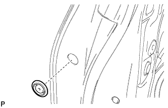
Remove the hole plug.
-
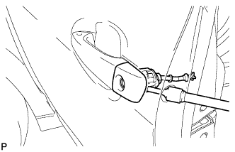
Using a T30 "TORX" socket wrench, loosen the screw and remove the front door outside handle cover with lock cylinder assembly.
Tech Tips
The screw cannot be removed because it is integrated into the front door outside handle frame sub-assembly.
-
-
REMOVE FRONT DOOR LOCK ASSEMBLY (w/o Double Locking System)
-
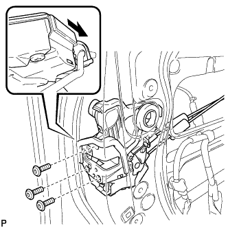
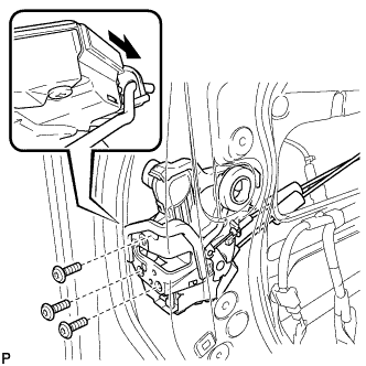
Using a T30 "TORX" socket wrench, remove the 3 screws.
-
Slide the front door lock assembly downward, and remove the front door lock assembly and cables as a unit.
-
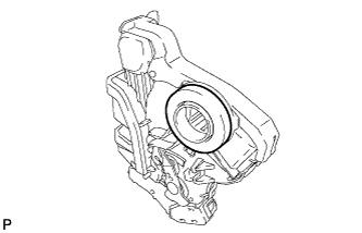
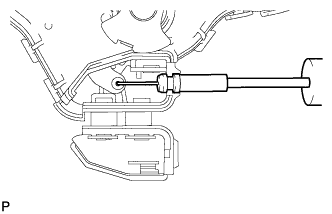
Remove the door lock wiring harness seal from the front door lock assembly.
-
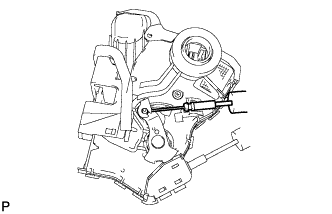
Remove the front door lock remote control cable assembly.
-
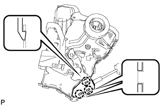
Using a screwdriver, disengage the 3 claws.
Tech Tips
Tape the screwdriver tip before use.
-
Remove the front door inside locking cable assembly.
-
-
REMOVE FRONT DOOR LOCK ASSEMBLY (w/ Double Locking System)
-
Using a T30 "TORX" socket wrench, remove the 3 screws.
-
Slide the front door lock assembly downward, and remove the front door lock assembly and cables as a unit.
-
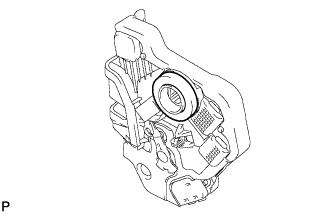
Remove the door lock wiring harness seal from the front door lock assembly.
-
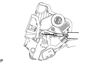
Remove the front door lock remote control cable assembly.
-
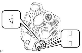
Using a screwdriver, disengage the 3 claws.
Tech Tips
Tape the screwdriver tip before use.
-
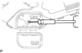
Remove the front door inside locking cable assembly.
-