CAN COMMUNICATION SYSTEM TERMINALS OF ECU

Note
-
Turn the power switch off before measuring the resistances between CAN bus main wires and between CAN bus branch wires.
-
Turn the power switch off before inspecting CAN bus wires for a ground short.
-
After the power switch is turned off, check that the key reminder warning system and light reminder warning system are not operating.
-
Before measuring the resistance, leave the vehicle as is for at least 1 minute and do not operate the power switch, any other switches or the doors. If any doors need to be opened in order to check connectors, open the doors and leave them open.
-
This section describes the standard CAN values for all CAN related components.
Tech Tips
-
Operating the power switch, any other switches or a door triggers related ECU and sensor communication on the CAN. This communication will cause the resistance value to change.
-
Even after DTCs are cleared, if a DTC is stored again after driving the vehicle for a while, the malfunction may be occurring due to vibration of the vehicle. In such a case, wiggling the ECUs or wire harness while performing the inspection below may help determine the cause of the malfunction.
-
CAN NO. 1 JUNCTION CONNECTOR (for LHD)
-
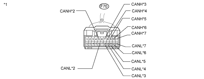
Check the CAN No. 1 junction connector.
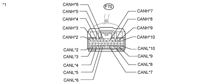
Text in Illustration *1 Front view of wire harness connector
(to CAN No. 1 Junction Connector)
*2 to Power Steering ECU *3 to Steering Angle Sensor *4 to DLC3 *5 to Combination Meter *6 to Main Body ECU *7 to CAN No. 2 Junction Connector *8 to Power Management Control ECU *9 to Center Airbag Sensor Assembly *10 to Yaw Rate Sensor -
Check the connection diagram of the components which are connected to the CAN No. 1 junction connector.
Terminal No. (Symbol) Wiring Color Connected to F70-1 (CANH) G Power steering ECU F70-12 (CANL) R F70-2 (CANH) BE Steering angle sensor F70-13 (CANL) R F70-3 (CANH) V DLC3 F70-14 (CANL) R F70-4 (CANH) P Combination meter F70-15 (CANL) R F70-5 (CANH) Y Main body ECU F70-16 (CANL) R F70-7 (CANH) B CAN No. 2 junction connector F70-18 (CANL) R F70-9 (CANH) LG Power management control ECU F70-20 (CANL) R F70-10 (CANH) R Center airbag sensor assembly F70-21 (CANL) L F70-11 (CANH) BR Yaw rate sensor F70-22 (CANL) R
-
-
CAN NO. 2 JUNCTION CONNECTOR (for LHD)
-
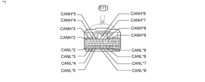
Check the CAN No. 2 junction connector.
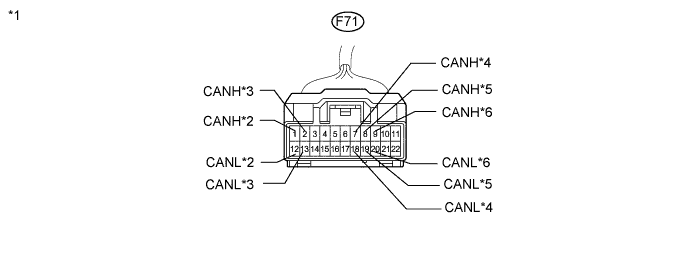
Text in Illustration *1 Front view of wire harness connector
(to CAN No. 2 Junction Connector)
*2 to Skid Control ECU *3 to Certification ECU *4 to CAN No. 1 Junction Connector *5
-
to Multi-media Module Receiver Assembly*1
-
to Radio Receiver Assembly*2
*6 to ECM *1: w/ Navigation system
*2: w/ Audio and visual system (w/ Multi-display)
-
-
Check the connection diagram of the components which are connected to the CAN No. 2 junction connector.
Terminal No. (Symbol) Wiring Color Connected to F71-1 (CANH) GR Skid control ECU F71-12 (CANL) R F71-2 (CANH) LG Certification ECU F71-13 (CANL) R F71-7 (CANH) B CAN No. 1 junction connector F71-18 (CANL) R F71-8 (CANH) SB
-
Multi-media module receiver assembly*1
-
Radio receiver assembly*2
F71-19 (CANL) R F71-9 (CANH) GR ECM F71-20 (CANL) R *1: w/ Navigation system
*2: w/ Audio and visual system (w/ Multi-display)
-
-
-
CAN NO. 3 JUNCTION CONNECTOR (for LHD)
-
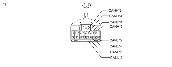
Check the CAN No. 3 junction connector.
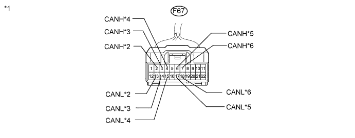
Text in Illustration *1 Front view of wire harness connector
(to CAN No. 3 Junction Connector)
*2 to Suspension Control ECU*1 *3 to Seat Belt Control ECU*2 *4
-
to Parking Assist ECU*3
-
to Clearance Warning ECU*4
*5 to CAN No. 4 Junction Connector *6 to Power Management Control ECU *1: w/ Air Suspension System
*2: w/ Pre-crash Safety System
*3: w/ Parking Assist Monitor System (w/ Side Monitor System)
*4: w/ LEXUS Parking Assist-sensor System (w/o Side Monitor System)
-
-
Check the connection diagram of the components which are connected to the CAN No. 3 junction connector.
Terminal No. (Symbol) Wiring Color Connected to F67-2 (CANH) P Suspension control ECU*1 F67-13 (CANL) L F67-3 (CANH) V Seat belt control ECU*2 F67-14 (CANL) L F67-4 (CANH) Y
-
Parking assist ECU*3
-
Clearance warning ECU*4
F67-15 (CANL) L F67-6 (CANH) BR CAN No. 4 junction connector F67-17 (CANL) L F67-7 (CANH) G Power management control ECU F67-18 (CANL) L *1: w/ Air Suspension System
*2: w/ Pre-crash Safety System
*3: w/ Parking Assist Monitor System (w/ Side Monitor System)
*4: w/ LEXUS Parking Assist-sensor System (w/o Side Monitor System)
-
-
-
CAN NO. 4 JUNCTION CONNECTOR (for LHD)
-
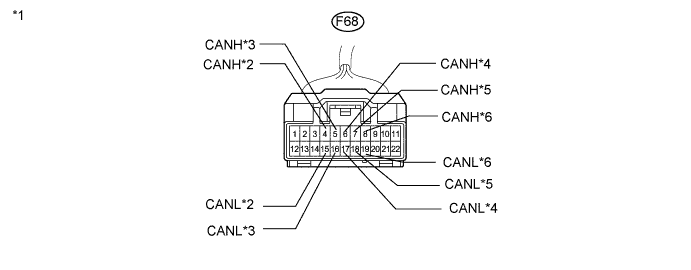
Check the CAN No. 4 junction connector.
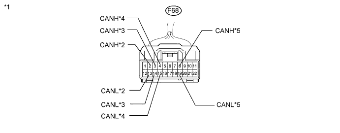
Text in Illustration *1 Front view of wire harness connector
(to CAN No. 4 Junction Connector)
*2 to Driving Support ECU*1 *3 to AFS ECU*2*3 *4 to CAN No. 3 Junction Connector *5 to CAN No. 5 Junction Connector - - *1: w/ Dynamic Radar Cruise Control System
*2: w/ Automatic Headlight Beam Level Control System
*3: w/ AFS (Adaptive Front-lighting System)
-
Check the connection diagram of the components which are connected to the CAN No. 4 junction connector.
Terminal No. (Symbol) Wiring Color Connected to F68-2 (CANH) BE Driving support ECU*1 F68-13 (CANL) L F68-3 (CANH) B AFS ECU*2*3 F68-14 (CANL) L F68-4 (CANH) BR CAN No. 3 junction connector F68-15 (CANL) L F68-8 (CANH) GR CAN No. 5 junction connector F68-19 (CANL) L *1: w/ Dynamic Radar Cruise Control System
*2: w/ Automatic Headlight Beam Level Control System
*3: w/ AFS (Adaptive Front-lighting System)
-
-
CAN NO. 1 JUNCTION CONNECTOR (for RHD)
-
Check the CAN No. 1 junction connector.
Text in Illustration *1 Front view of wire harness connector
(to CAN No. 1 Junction Connector)
*2 to Main Body ECU *3 to CAN No. 2 Junction Connector *4 to Multi-media Module Receiver Assembly*1 *5 to Power Management Control ECU *6 to Center Airbag Sensor Assembly *7 to Yaw Rate Sensor - - *1: w/ Navigation system
-
Check the connection diagram of the components which are connected to the CAN No. 1 junction connector.
Terminal No. (Symbol) Wiring Color Connected to F70-5 (CANH) Y Main body ECU F70-16 (CANL) R F70-7 (CANH) B CAN No. 2 junction connector F70-18 (CANL) R F70-8 (CANH) SB Multi-media module receiver assembly*1 F70-19 (CANL) R F70-9 (CANH) LG Power management control ECU F70-20 (CANL) R F70-10 (CANH) R Center airbag sensor assembly F70-21 (CANL) L F70-11 (CANH) BR Yaw rate sensor F70-22 (CANL) R *1: w/ Navigation system
-
-
CAN NO. 2 JUNCTION CONNECTOR (for RHD)
-
Check the CAN No. 2 junction connector.
Text in Illustration *1 Front view of wire harness connector
(to CAN No. 2 Junction Connector)
*2 to Skid Control ECU *3 to Certification ECU *4 to DLC3 *5 to Combination Meter *6 to Steering Angle Sensor *7 to Power Steering ECU *8 to CAN No. 1 Junction Connector *9 to ECM - - -
Check the connection diagram of the components which are connected to the CAN No. 2 junction connector.
Terminal No. (Symbol) Wiring Color Connected to F71-1 (CANH) GR Skid control ECU F71-12 (CANL) R F71-2 (CANH) LG Certification ECU F71-13 (CANL) R F71-3 (CANH) V DLC3 F71-14 (CANL) R F71-4 (CANH) P Combination meter F71-15 (CANL) R F71-5 (CANH) BE Steering angle sensor F71-16 (CANL) R F71-6 (CANH) G Power steering ECU F71-17 (CANL) R F71-7 (CANH) B CAN No. 1 junction connector F71-18 (CANL) R F71-8 (CANH) GR ECM F71-19 (CANL) R
-
-
CAN NO. 3 JUNCTION CONNECTOR (for RHD)
-
Check the CAN No. 3 junction connector.
Text in Illustration *1 Front view of wire harness connector
(to CAN No. 3 Junction Connector)
*2 to CAN No. 4 Junction Connector *3 to Driving Support ECU*1 *4 to AFS ECU*2*3 *5 to Power Management Control ECU - - *1: w/ Dynamic Radar Cruise Control System
*2: w/ Automatic Headlight Beam Level Control System
*3: w/ AFS (Adaptive Front-lighting System)
-
Check the connection diagram of the components which are connected to the CAN No. 3 junction connector.
Terminal No. (Symbol) Wiring Color Connected to F67-6 (CANH) BR CAN No. 4 junction connector F67-17 (CANL) L F67-7 (CANH) BE Driving support ECU*1 F67-18 (CANL) L F67-8 (CANH) B AFS ECU*2*3 F67-19 (CANL) L F67-9 (CANH) G Power management control ECU F67-20 (CANL) L *1: w/ Dynamic Radar Cruise Control System
*2: w/ Automatic Headlight Beam Level Control System
*3: w/ AFS (Adaptive Front-lighting System)
-
-
CAN NO. 4 JUNCTION CONNECTOR (for RHD)
-
Check the CAN No. 4 junction connector.
Text in Illustration *1 Front view of wire harness connector
(to CAN No. 4 Junction Connector)
*2 to CAN No. 3 Junction Connector *3 to Seat Belt Control ECU*1 *4
-
to Parking Assist ECU*2
-
to Clearance Warning ECU*3
*5 to Suspension Control ECU*4 *6 to CAN No. 5 Junction Connector *1: w/ Pre-crash Safety System
*2: w/ Parking Assist Monitor System (w/ Side Monitor System)
*3: w/ LEXUS Parking Assist-sensor System (w/o Side Monitor System)
*4: w/ Air Suspension System
-
-
Check the connection diagram of the components which are connected to the CAN No. 4 junction connector.
Terminal No. (Symbol) Wiring Color Connected to F68-4 (CANH) BR CAN No. 3 junction connector F68-15 (CANL) L F68-5 (CANH) V Seat belt control ECU*1 F68-16 (CANL) L F68-6 (CANH) Y
-
Parking assist ECU*2
-
Clearance warning ECU*3
F68-17 (CANL) L F68-7 (CANH) P Suspension control ECU*4 F68-18 (CANL) L F68-8 (CANH) GR CAN No. 5 junction connector F68-19 (CANL) L *1: w/ Pre-crash Safety System
*2: w/ Parking Assist Monitor System (w/ Side Monitor System)
*3: w/ LEXUS Parking Assist-sensor System (w/o Side Monitor System)
*4: w/ Air Suspension System
-
-
-
CAN NO. 5 JUNCTION CONNECTOR
Tech Tips
- The connectors connected to the CAN junction connectors can be distinguished according to the color of the communication bus wires.
- Reconnecting the connectors to non-specified positions on the CAN junction connectors does not affect system operation. However, it is preferred to reconnect the connectors to their original positions to avoid negative effects on the wiring such as tension on the wiring harnesses, and to make future maintenance easier.
-
Check the CAN No. 5 junction connectors.
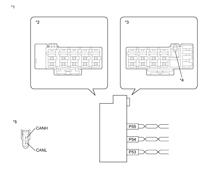
Text in Illustration *1 Component without harness connected
(CAN No. 5 Junction Connector)
*2 CAN No. 5 Junction Connector B Side *3 CAN No. 5 Junction Connector A Side *4 Ground Terminal *5 Front view of wire harness connector
(to CAN No. 5 Junction Connector)
- - -
Check the connection diagram of the components which are connected to the CAN No. 5 junction connector.
Terminal No. (Symbol) Wiring Color Connected to P56-1 W-B Ground P55-1 (CANH) L CAN No. 4 junction connector P55-2 (CANL) Y P54-1 (CANH) V Rear active stabilizer control ECU*1 P54-2 (CANL) LG P53-1 (CANH) R Front active stabilizer control ECU*1 P53-2 (CANL) G *1: w/ Active Stabilizer Suspension System
-
-
CAN NO. 6 JUNCTION CONNECTOR
-
Check the CAN No. 6 junction connector.
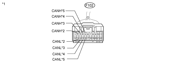
Text in Illustration *1 Front view of wire harness connector
(to CAN No. 6 Junction Connector)
*2 to Front Power Seat Switch LH*1 *3 to CAN No. 7 Junction Connector
(w/ Power Back Door System)
*3 to CAN No. 8 Junction Connector
(w/o Power Back Door System)
*4 to Main Body ECU *5 to Outer Mirror Control ECU LH *1: w/ Position Memory System
-
Check the connection diagram of the components which are connected to the CAN No. 6 junction connector.
Terminal No. (Symbol) Wiring Color Connected to F102-2 (CANH) G Front power seat switch LH*1 F102-13 (CANL) W F102-3 (CANH) B CAN No. 7 junction connector
(w/ power back door system)
F102-14 (CANL) W F102-3 (CANH) B CAN No. 8 junction connector
(w/o power back door system)
F102-14 (CANL) W F102-4 (CANH) BE Main body ECU F102-15 (CANL) W F102-5 (CANH) LG Outer mirror control ECU LH F102-16 (CANL) W *1: w/ Position Memory System
-
-
CAN NO. 7 JUNCTION CONNECTOR
-
Check the CAN No. 7 junction connector.
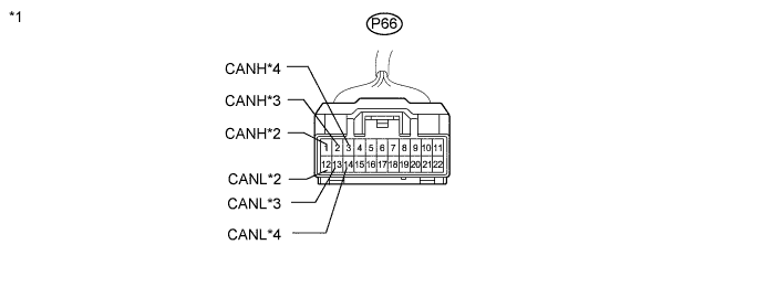
Text in Illustration *1 Front view of wire harness connector
(to CAN No. 7 Junction Connector)
*2 to CAN No. 8 Junction Connector *3 Power Back Door ECU*1
(Back Door Motor Unit)
*4 to CAN No. 6 Junction Connector *1: w/ Power Back Door System
-
Check the connection diagram of the components which are connected to the CAN No. 7 junction connector.
Terminal No. (Symbol) Wiring Color Connected to P66-1 (CANH) B CAN No. 8 junction connector P66-12 (CANL) W P66-2 (CANH) B Power back door ECU*1
(Back door motor unit)
P66-13 (CANL) W P66-3 (CANH) B CAN No. 6 junction connector P66-14 (CANL) W *1: w/ Power Back Door System
-
-
CAN NO. 8 JUNCTION CONNECTOR
-
Check the CAN No. 8 junction connector.
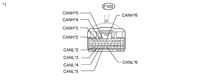
Text in Illustration *1 Front view of wire harness connector
(to CAN No. 8 Junction Connector)
*2 to Front Power Seat Switch RH*1 *3 to Tilt and Telescopic ECU
(Multiplex Tilt and Telescopic ECU)
*4 to CAN No. 7 Junction Connector*2 *4 to CAN No. 6 Junction Connector*3 *5 to Outer Mirror Control ECU RH *6 to Tire Pressure Warning ECU and Receiver*4 - - *1: w/ Position Memory System
*2: w/ Power Back Door System
*3: w/o Power Back Door System
*4: w/ Tire Pressure Warning System
-
Check the connection diagram of the components which are connected to the CAN No. 8 junction connector.
Terminal No. (Symbol) Wiring Color Connected to F103-2 (CANH) G Front power seat switch RH*1 F103-13 (CANL) W F103-3 (CANH) BE Tilt and telescopic ECU
(Multiplex tilt and telescopic ECU)
F103-14 (CANL) W F103-4 (CANH) B CAN No. 7 junction connector*2 F103-15 (CANL) W F103-4 (CANH) B CAN No. 6 junction connector*3 F103-15 (CANL) W F103-5 (CANH) LG Outer mirror control ECU RH F103-16 (CANL) W F103-6 (CANH) V Tire pressure warning ECU and receiver*4 F103-17 (CANL) W *1: w/ Position Memory System
*2: w/ Power back door system
*3: w/o Power back door system
*4: w/ Tire Pressure Warning System
-
-
CAN NO. 9 JUNCTION CONNECTOR
-
Check the CAN No. 9 junction connector.
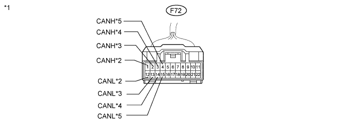
Text in Illustration *1 Front view of wire harness connector
(to CAN No. 9 Junction Connector)
*2 to Air Conditioning Amplifier *3 to Power Management Control ECU *4 to ECM *5 to Skid Control ECU - - -
Check the connection diagram of the components which are connected to the CAN No. 9 junction connector.
Terminal No. (Symbol) Wiring Color Connected to F72-1 (CANH) B Air conditioning amplifier F72-12 (CANL) W F72-2 (CANH) V Power management control ECU F72-13 (CANL) W F72-3 (CANH) G ECM F72-14 (CANL) W F72-4 (CANH) P Skid control ECU F72-15 (CANL) W
-
-
CAN NO. 10 JUNCTION CONNECTOR (w/ Active Stabilizer Suspension System)
Tech Tips
- The connectors connected to the CAN junction connectors can be distinguished according to the color of the communication bus wires.
- Reconnecting the connectors to non-specified positions on the CAN junction connectors does not affect system operation. However, it is preferred to reconnect the connectors to their original positions to avoid negative effects on the wiring such as tension on the wiring harnesses, and to make future maintenance easier.
-
Check the CAN No. 10 junction connectors.
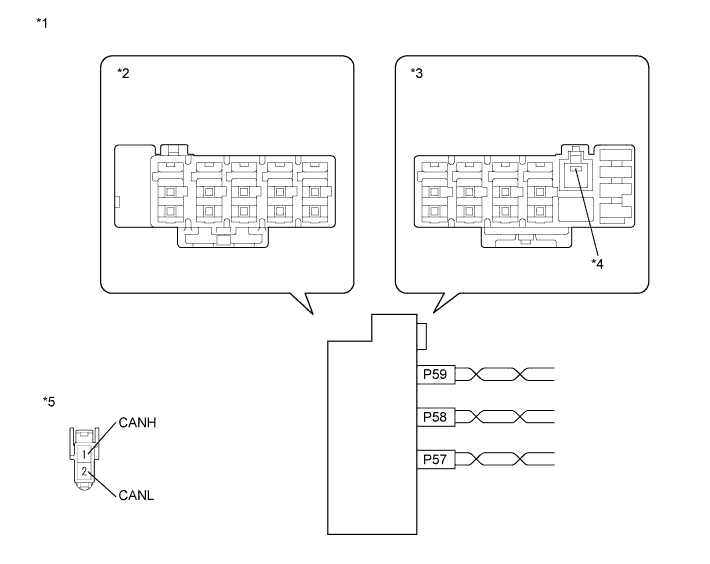
Text in Illustration *1 Component without harness connected
(CAN No. 10 Junction Connector)
*2 CAN No. 10 Junction Connector B Side *3 CAN No. 10 Junction Connector A Side *4 Ground Terminal *5 Front view of wire harness connector
(to CAN No. 10 Junction Connector)
- - -
Check the connection diagram of the components which are connected to the CAN No. 10 junction connector.
Terminal No. (Symbol) Wiring Color Connected to P60-1 W-B Ground P59-1 (CANH) B Skid control ECU P59-2 (CANL) W P58-1 (CANH) B Rear active stabilizer control ECU P58-2 (CANL) W P57-1 (CANH) L Front active stabilizer control ECU P57-2 (CANL) Y
-
-
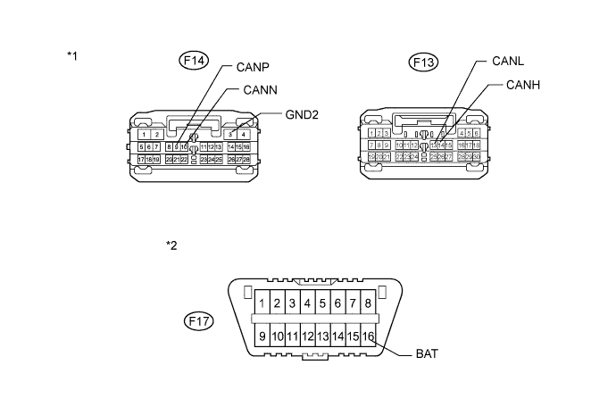
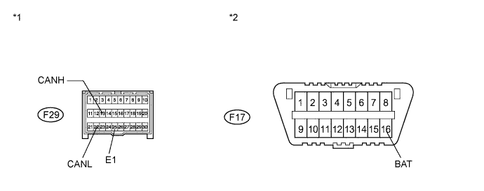
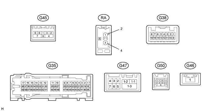
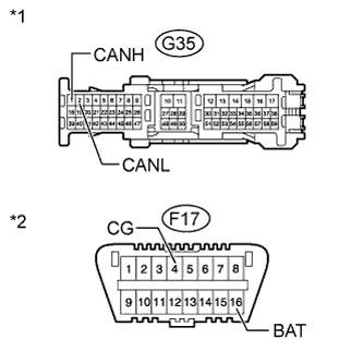
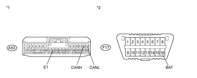
DLC3
-
Measure the resistance according to the value(s) in the table below.
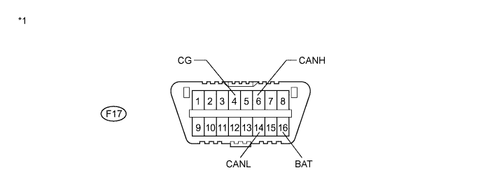
Text in Illustration *1 DLC3
-
-
ECM
-
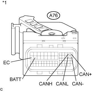
Text in Illustration *1 Front view of wire harness connector
(to ECM)
Disconnect the connector of the ECM.
-
Measure the resistance according to the value(s) in the table below.
-
-
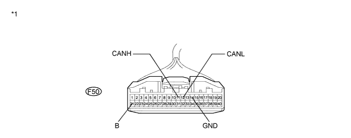
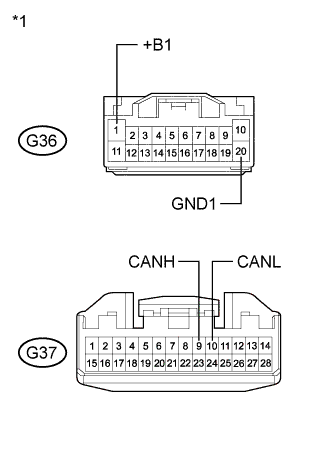
MAIN BODY ECU (MULTIPLEX NETWORK BODY ECU)
-
Disconnect the connectors of the main body ECU.
Text in Illustration *1 Front view of wire harness connector
(to Main Body ECU)
*2 DLC3 -
Measure the resistance according to the value(s) in the table below.
-
-
COMBINATION METER
-
Text in Illustration *1 Front view of wire harness connector
(to Combination Meter)
Disconnect the connector of the combination meter.
-
Measure the resistance according to the value(s) in the table below.
-
-
POWER STEERING ECU
-
Disconnect the connectors of the power steering ECU.
Text in Illustration *1 Front view of wire harness connector
(to Power Steering ECU)
-
Measure the resistance according to the value(s) in the table below.
-
-
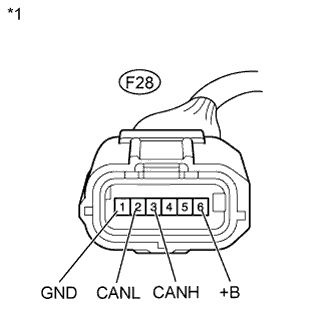
AIR CONDITIONING AMPLIFIER
-
Disconnect the connector of the air conditioning amplifier.
Text in Illustration *1 Front view of wire harness connector
(to Air Conditioning Amplifier)
-
Measure the resistance according to the value(s) in the table below.
-
-
CENTER AIRBAG SENSOR ASSEMBLY
-
Disconnect the connector of the center airbag sensor assembly.
Text in Illustration *1 Front view of wire harness connector
(to Center Airbag Sensor Assembly)
*2 DLC3 -
Measure the resistance according to the value(s) in the table below.
-
-
SKID CONTROL ECU
-
Text in Illustration *1 Front view of wire harness connector
(to Skid Control ECU)
Disconnect the connectors of the skid control ECU.
-
Measure the resistance according to the value(s) in the table below.
-
-
STEERING ANGLE SENSOR
-
Text in Illustration *1 Front view of wire harness connector
(to Steering Angle Sensor)
Disconnect the connector of the steering angle sensor.
-
Measure the resistance according to the value(s) in the table below.
-
-
YAW RATE SENSOR
-
Text in Illustration *1 Front view of wire harness connector
(to Yaw Rate Sensor)
Disconnect the connector of the yaw rate sensor.
-
Measure the resistance according to the value(s) in the table below.
-
-
CERTIFICATION ECU (SMART KEY ECU)
-
Disconnect the connector of the certification ECU.
Text in Illustration *1 Front view of wire harness connector
(to Certification ECU)
-
Measure the resistance according to the value(s) in the table below.
-
-
RADIO RECEIVER ASSEMBLY
-
Text in Illustration *1 Front view of wire harness connector
(to Radio Receiver Assembly)
Disconnect the connectors of the radio receiver assembly.
-
Measure the resistance according to the value(s) in the table below.
-
-
MULTI-MEDIA MODULE RECEIVER ASSEMBLY
-
Text in Illustration *1 Front view of wire harness connector
(to Multi-media Module Receiver Assembly)
*2 DLC3 Disconnect the connector of the multi-media module receiver assembly.
-
Measure the resistance according to the value(s) in the table below.
-
-
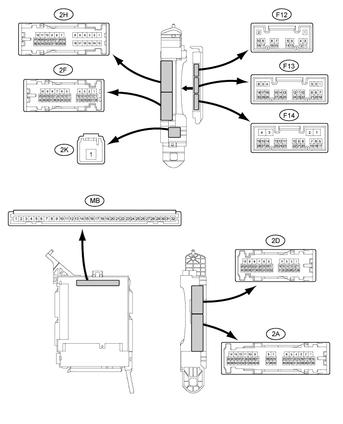
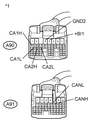
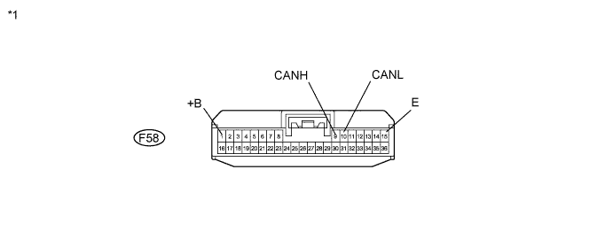
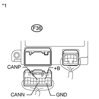
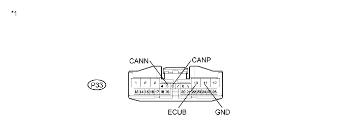
POWER MANAGEMENT CONTROL ECU
-
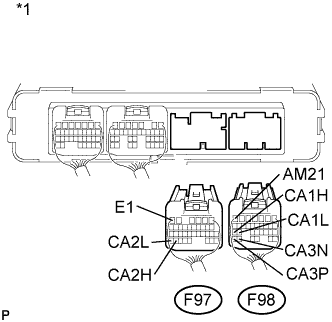
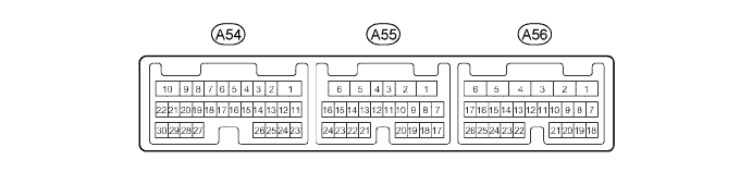
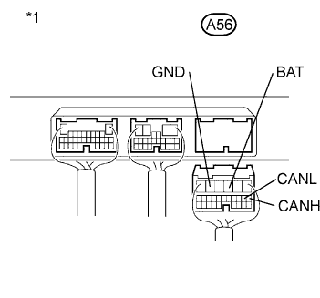
Text in Illustration *1 Rear view of wire harness connector
(to Power Management control ECU)
Disconnect the connectors of the power management control ECU.
-
Measure the resistance according to the value(s) in the table below.
Standard Resistance for CAN No. 1 Bus Main Wire Terminal No. (Symbol) Wiring Color Terminal Description Condition Specified Condition F98-25 (CA1H) - F98-24 (CA1L) LG - R HIGH-level CAN bus wire - LOW-level CAN bus wire Power switch off 108 to 132 Ω F98-25 (CA1H) - F98-7 (AM21) LG - R HIGH-level CAN bus wire - Auxiliary battery positive (+) Cable disconnected from negative (-) auxiliary battery terminal 6 kΩ or higher F98-24 (CA1L) - F98-7 (AM21) R - R LOW-level CAN bus wire - Auxiliary battery positive (+) Cable disconnected from negative (-) auxiliary battery terminal 6 kΩ or higher F98-25 (CA1H) - F97-6 (E1) LG - BR HIGH-level CAN bus wire - Ground Power switch off 200 Ω or higher F98-24 (CA1L) - F97-6 (E1) R - BR LOW-level CAN bus wire - Ground Power switch off 200 Ω or higher for CAN No. 2 Bus Main Wire Terminal No. (Symbol) Wiring Color Terminal Description Condition Specified Condition F97-34 (CA2H) - F97-35 (CA2L) G - L HIGH-level CAN bus wire - LOW-level CAN bus wire Power switch off 108 to 132 Ω F97-34 (CA2H) - F98-7 (AM21) G - R HIGH-level CAN bus wire - Auxiliary battery positive (+) Cable disconnected from negative (-) auxiliary battery terminal 6 kΩ or higher F97-35 (CA2L) - F98-7 (AM21) L - R LOW-level CAN bus wire - Auxiliary battery positive (+) Cable disconnected from negative (-) auxiliary battery terminal 6 kΩ or higher F97-34 (CA2H) - F97-6 (E1) G - BR HIGH-level CAN bus wire - Ground Power switch off 200 Ω or higher F97-35 (CA2L) - F97-6 (E1) L - BR LOW-level CAN bus wire - Ground Power switch off 200 Ω or higher for Power Management Bus Main Wire Terminal No. (Symbol) Wiring Color Terminal Description Condition Specified Condition F98-31 (CA3P) - F98-30 (CA3N) V - W HIGH-level CAN bus wire - LOW-level CAN bus wire Power switch off 108 to 132 Ω F98-31 (CA3P) - F98-7 (AM21) V - R HIGH-level CAN bus wire - Auxiliary battery positive (+) Cable disconnected from negative (-) auxiliary battery terminal 6 kΩ or higher F98-30 (CA3N) - F98-7 (AM21) W - R LOW-level CAN bus wire - Auxiliary battery positive (+) Cable disconnected from negative (-) auxiliary battery terminal 6 kΩ or higher F98-31 (CA3P) - F97-6 (E1) V - BR HIGH-level CAN bus wire - Ground Power switch off 200 Ω or higher F98-30 (CA3N) - F97-6 (E1) W - BR LOW-level CAN bus wire - Ground Power switch off 200 Ω or higher -
-
AFS ECU (HEADLIGHT SWIVEL ECU)
-
Disconnect the connector of the AFS ECU.
Text in Illustration *1 Front view of wire harness connector
(to AFS ECU)
*2 DLC3 -
Measure the resistance according to the value(s) in the table below.
-
-
SUSPENSION CONTROL ECU
-
Text in Illustration *1 Rear view of wire harness connector
(to Suspension Control ECU)
Disconnect the connector of the suspension control ECU.
-
Measure the resistance according to the value(s) in the table below.
-
-
SEAT BELT CONTROL ECU
Text in Illustration *1 Front view of wire harness connector
(to Seat Belt Control ECU)
-
Disconnect the connectors of the seat belt control ECU.
-
Measure the resistance according to the value(s) in the table below.
-
-
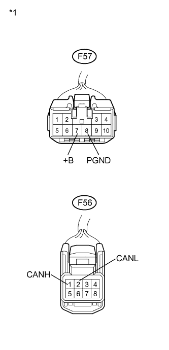
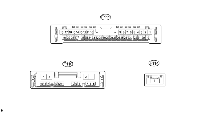
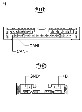
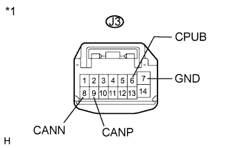
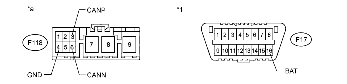
DRIVING SUPPORT ECU
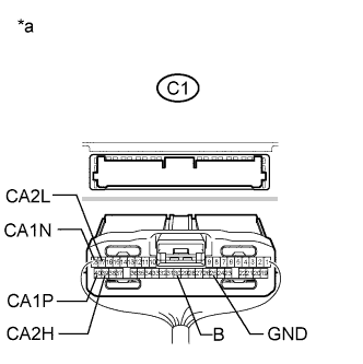
Text in Illustration *a Rear view of wire harness connector
(to Driving Support ECU)
-
Disconnect the connector of the driving support ECU.
-
Measure the resistance according to the value(s) in the table below.
-
-
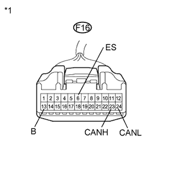
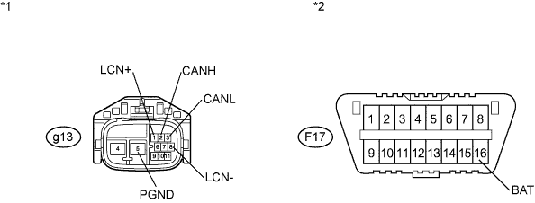
MILLIMETER WAVE RADAR SENSOR ASSEMBLY
-
Disconnect the connector of the millimeter wave radar sensor assembly.
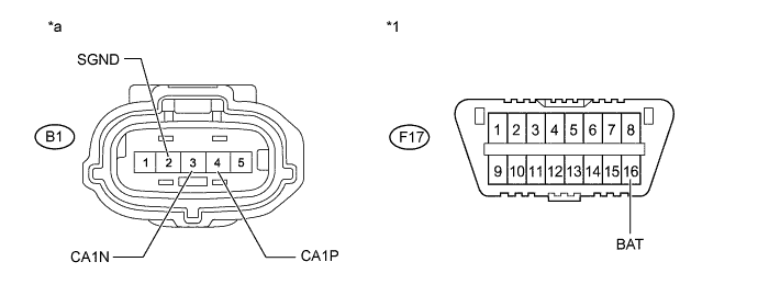
Text in Illustration *1 DLC3 - - *a Front view of wire harness connector
(to Millimeter Wave Radar Sensor Assembly)
- - -
Measure the resistance according to the value(s) in the table below.
-
-
PARKING ASSIST ECU
-
Text in Illustration *1 Rear view of wire harness connector
(to Parking Assist ECU)
Disconnect the connector of the parking assist ECU.
-
Measure the resistance according to the value(s) in the table below.
-
-
CLEARANCE WARNING ECU
-
Disconnect the connector of the clearance warning ECU.
Text in Illustration *1 Front view of wire harness connector
(to Clearance Warning ECU)
*2 DLC3 -
Measure the resistance according to the value(s) in the table below.
-
-
TILT AND TELESCOPIC ECU (MULTIPLEX TILT AND TELESCOPIC ECU)
Text in Illustration *1 Rear view of wire harness connector
(to Multiplex Tilt and Telescopic ECU)
-
Disconnect the connector of the multiplex tilt and telescopic ECU.
-
Measure the resistance according to the value(s) in the table below.
-
-
OUTER MIRROR CONTROL ECU RH
-

Text in Illustration *1 Front view of wire harness connector
(to Outer Mirror Control ECU RH)
Disconnect the connector of the outer mirror control ECU RH.
-
Measure the resistance according to the value(s) in the table below.
-
-
OUTER MIRROR CONTROL ECU LH
-
Text in Illustration *1 Front view of wire harness connector
(to Outer Mirror Control ECU LH)
Disconnect the connector of the outer mirror control ECU LH.
-
Measure the resistance according to the value(s) in the table below.
-
-
FRONT POWER SEAT SWITCH RH
-
Disconnect the connectors of the front power seat switch RH.
Text in Illustration *1 Front view of wire harness connector
(to Front Power Seat Switch RH)
-
Measure the resistance according to the value(s) in the table below.
-
-
FRONT POWER SEAT SWITCH LH
-
Disconnect the connectors of the front power seat switch LH.
Text in Illustration *1 Front view of wire harness connector
(to Front Power Seat Switch LH)
-
Measure the resistance according to the value(s) in the table below.
-
-
POWER BACK DOOR ECU (BACK DOOR MOTOR UNIT)
-
Disconnect the connector of the power back door ECU (back door motor unit).
Text in Illustration *1 Front view of wire harness connector
(to Power Back Door ECU)
-
Measure the resistance according to the value(s) in the table below.
-
-
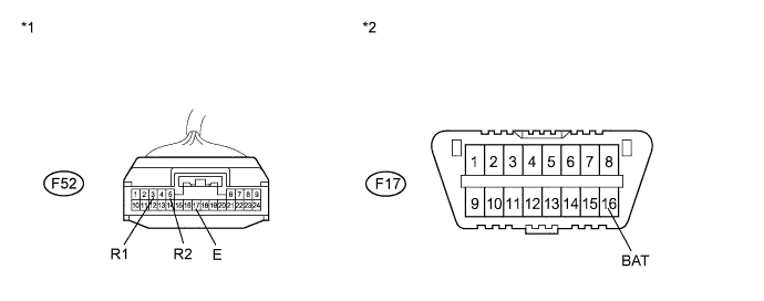
TIRE PRESSURE WARNING ECU AND RECEIVER
-
Disconnect the connector of the tire pressure warning ECU and receiver.
Text in Illustration *1 DLC3 - - *a Front view of wire harness connector
(to Front Active Stabilizer Control ECU)
- - -
Measure the resistance according to the value(s) in the table below.
-
-
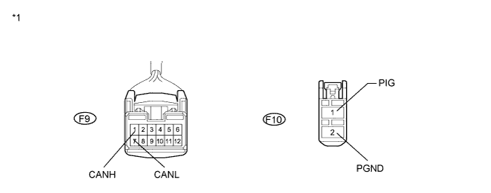
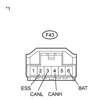
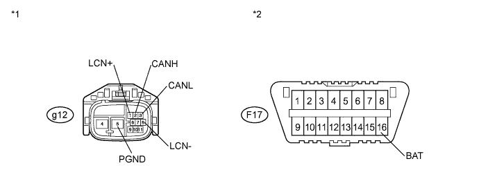
FRONT ACTIVE STABILIZER CONTROL ECU
-
Disconnect the connector of the front active stabilizer control ECU.
Text in Illustration *1 Front view of wire harness connector
(to Front Active Stabilizer Control ECU)
*2 DLC3 -
Measure the resistance according to the value(s) in the table below.
-
-
REAR ACTIVE STABILIZER CONTROL ECU
-
Disconnect the connector of the rear active stabilizer control ECU.
Text in Illustration *1 Front view of wire harness connector
(to Rear Active Stabilizer Control ECU)
*2 DLC3 -
Measure the resistance according to the value(s) in the table below.
-