CLEARANCE WARNING ECU REMOVAL

-
PRECAUTION
Note
After turning the power switch off, waiting time may be required before disconnecting the cable from the auxiliary battery negative (-) terminal. Therefore, make sure to read the disconnecting the cable from the auxiliary battery negative (-) terminal notices before proceeding with work Click here.
-
REMOVE REAR DECK FLOOR BOX
-
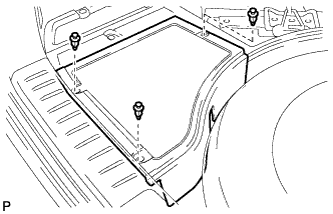
Remove the 3 clips and the rear deck floor box.
-
-
DISCONNECT CABLE FROM NEGATIVE AUXILIARY BATTERY TERMINAL
CAUTION:
Wait at least 90 seconds after disconnecting the cable from the auxiliary battery negative (-) terminal to disable the SRS system.
Note
When disconnecting the cable, some systems need to be initialized after the cable is reconnected Click here.
-
REMOVE SHIFT LEVER KNOB SUB-ASSEMBLY
-
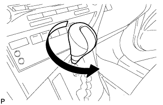
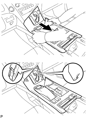
Turn the shift lever knob sub-assembly counterclockwise and remove the shift lever knob sub-assembly.
-
-
REMOVE UPPER CONSOLE PANEL SUB-ASSEMBLY
-
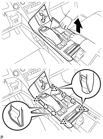
Move the shift lever to N.
-
Pull the upper console panel sub-assembly in the direction indicated by the arrow to disengage the 4 claws and 4 clips.
-
w/o Seat Heater System:
-
Disconnect the connector from the console box hole cover.
-
-
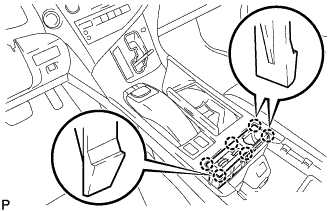
w/ Seat Heater System:
-
Disengage the 6 claws.
-
Disconnect the connector and remove the seat heater switch with console box hole cover.
-
-
Pull the upper console panel sub-assembly in the direction indicated by the arrow to disengage the 3 claws and 3 clips.
-
Disconnect each connector.
-
Disengage the clamp and remove the upper console panel sub-assembly.
-
-
REMOVE LOWER INSTRUMENT PANEL FINISH PANEL
-
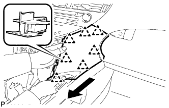
Pull the lower instrument panel finish panel in the direction indicated by the arrow to disengage the 7 clips and remove the lower instrument panel finish panel.
-
-
REMOVE FRONT DOOR SCUFF PLATE RH
Tech Tips
Use the same procedure for the RH side and LH side Click here.
-
REMOVE COWL SIDE TRIM SUB-ASSEMBLY RH
Tech Tips
Use the same procedure for the RH side and LH side Click here.
-
REMOVE NO. 2 INSTRUMENT PANEL UNDER COVER SUB-ASSEMBLY
-
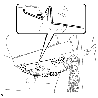
Disengage the 4 claws and 2 guides as shown in the illustration.
-
Disconnect the connector and remove the No. 2 instrument panel under cover sub-assembly.
-
-
REMOVE INSTRUMENT PANEL GARNISH RH (w/o Airbag Cut Off Switch)
Tech Tips
Use the same procedure for the RH side and LH side Click here.
-
REMOVE INSTRUMENT PANEL GARNISH RH (w/ Airbag Cut Off Switch)
-
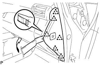
Using moulding remover B, disengage the 6 clips as shown in the illustration.
-
Disconnect the connector and remove the instrument panel garnish RH.
-
-
REMOVE FRONT PASSENGER SIDE KNEE AIRBAG ASSEMBLY
CAUTION:
When storing the front passenger side knee airbag assembly, keep the airbag deployment side facing upward.
-
Check that the power switch is off.
-
Check that the cable is disconnected from the negative (-) battery terminal.
CAUTION:
Wait at least 90 seconds after disconnecting the cable from the negative (-) battery terminal to disable the SRS system.
-
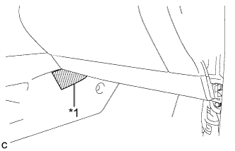
Text in Illustration *1 Protective Tape Put protective tape around the front passenger side knee airbag assembly.
-
Remove the 3 bolts.
-
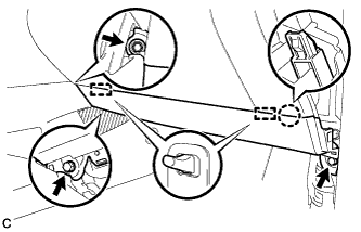
Disengage the claw and 2 pins to separate the front passenger side knee airbag assembly.
-
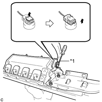
Text in Illustration *1 Protective Tape Using a screwdriver with the tip wrapped with protective tape, disconnect the airbag connector to remove the front passenger side knee airbag assembly.
Note
When disconnecting any airbag connector, take care not to damage the airbag wire harness.
-
-
REMOVE GLOVE COMPARTMENT DOOR ASSEMBLY
-
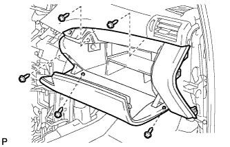
Remove the 5 screws <F>.
-
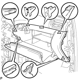
Disengage the claw, 4 clips and guide.
-
Disconnect each connector and remove the glove compartment door assembly.
-
-
DISCONNECT CONNECTOR HOLDER (for LHD)
-
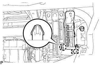
Disengage the clamp and disconnect the wire harness.
-
Remove the nut.
-
Disengage the claw and disconnect the connector holder.
-
-
REMOVE ECU INTEGRATION BOX
-
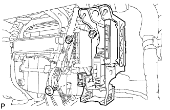
Remove the bolt, 2 nuts and ECU integration box.
-
-
REMOVE CLEARANCE WARNING ECU ASSEMBLY
-
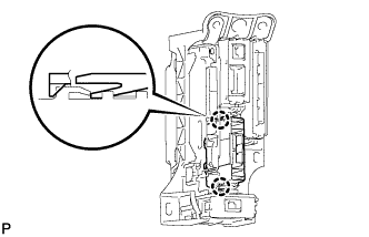
Disengage the 2 claws and remove the clearance warning ECU assembly.
-