YAW RATE AND ACCELERATION SENSOR REMOVAL

-
PRECAUTION
Note
After turning the power switch off, waiting time may be required before disconnecting the cable from the negative (-) auxiliary battery terminal. Therefore, make sure to read the disconnecting the cable from the negative (-) auxiliary battery terminal notices before proceeding with work Click here.
-
REMOVE REAR DECK FLOOR BOX
-
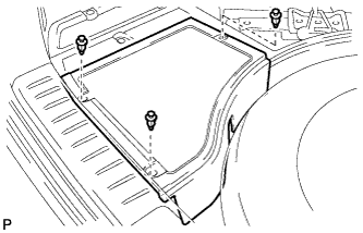
Remove the 3 clips and the rear deck floor box.
-
-
DISCONNECT CABLE FROM NEGATIVE AUXILIARY BATTERY TERMINAL
Note
When disconnecting the cable, some systems need to be initialized after the cable is reconnected Click here.
-
REMOVE REAR CONSOLE BOX ASSEMBLY
-
REMOVE FRONT DOOR SCUFF PLATE LH
-
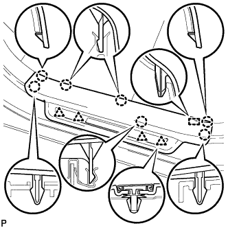
Disengage the 7 claws, 4 clips and guide, and remove the front door scuff plate LH.
Tech Tips
A part of the clip remains on the vehicle side.
-
w/ Illumination:
-
Disconnect the connector.
-
-
-
REMOVE COWL SIDE TRIM SUB-ASSEMBLY LH
-
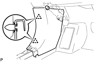
Remove the clip.
-
Disengage the 2 clips and remove the cowl side trim sub-assembly LH.
-
-
REMOVE INSTRUMENT PANEL GARNISH LH
-
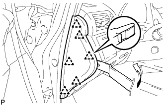
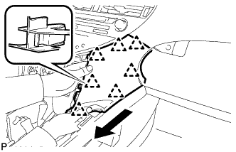
Using moulding remover B, disengage the 6 clips and remove the instrument panel garnish LH as shown in the illustration.
-
-
REMOVE NO. 1 SWITCH HOLE BASE
-
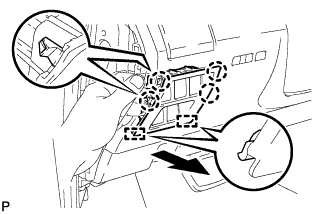
Push the No. 1 switch hole base in the direction indicated by the arrow to disengage the 4 claws and 2 guides.
-
Disconnect each connector and remove the No. 1 switch hole base.
-
-
REMOVE LOWER INSTRUMENT PANEL FINISH PANEL SUB-ASSEMBLY
-
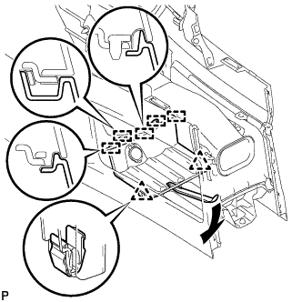
Disengage the 2 claws and open the cover as shown in the illustration.
-
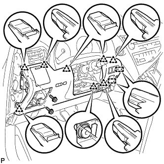
Remove the 2 screws <D>.
-
Disengage the 8 clips and 2 guides.
-
Disconnect each connector and remove the lower instrument panel finish panel sub-assembly.
-
-
REMOVE INSTRUMENT PANEL FINISH PANEL
-
Pull the instrument panel finish panel in the direction indicated by the arrow to disengage the claw, 2 clips and 2 guides, and remove the instrument panel finish panel.
-
-
REMOVE LOWER INSTRUMENT PANEL FINISH PANEL
-
Pull the lower instrument panel finish panel in the direction indicated by the arrow to disengage the 7 clips and remove the lower instrument panel finish panel.
-
-
REMOVE FRONT CONSOLE BOX COVER
-
Using moulding remover A, disengage the 2 clips and 5 guides.
-
Disconnect the connector and remove the front console box cover.
-
-
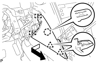
REMOVE CONSOLE BOX (for LHD)
-
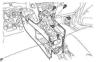
Remove the 5 screws <D>.
-
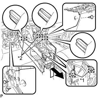
Text in Illustration *1 Clamp *2 Guide Disengage the 2 clamps.
-
Remove the 3 clips.
-
Disengage the 3 guides and remove the console box as shown in the illustration.
-
-
REMOVE CONSOLE BOX (for RHD)
-
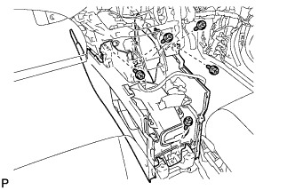
Remove the 5 screws <D>.
-
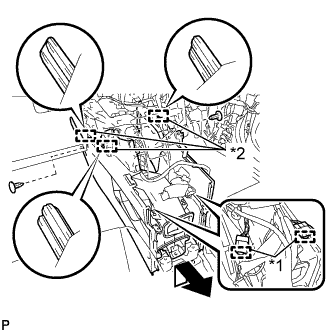
Text in Illustration *1 Clamp *2 Guide Disengage the 2 clamps.
-
Remove the 2 clips.
-
Disengage the 3 guides and remove the console box as shown in the illustration.
-
-
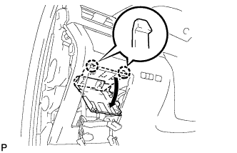
REMOVE YAW RATE AND ACCELERATION SENSOR
-
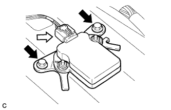
Remove the 2 bolts and yaw rate and acceleration sensor.
Note
Do not remove the installation nuts.
-
Disconnect the connector from the yaw rate and acceleration sensor.
-