If the sensor rotor needs to be replaced, replace it together with the rear axle hub and bearing assembly.
- Click here
INSTALL REAR SPEED SENSOR LH
-
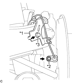
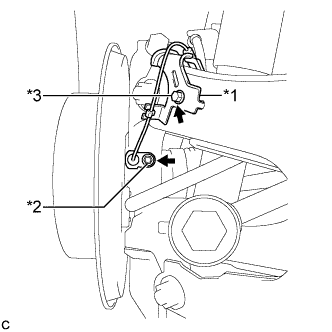
Install the No. 1 bracket and rear speed sensor to the rear trailing arm assembly and the rear axle carrier sub-assembly with the 2 bolts.
Table 1. Text in Illustration *1 No. 1 Bracket *2 Bolt A *3 Bolt B Bolt A 8.5 N*m 87 kgf*cm 75 in.*lbf Bolt B 8.0 N*m 82 kgf*cm 71 in.*lbf Note:
-
Prevent foreign matter from attaching to the rear speed sensor tip.
-
Clean the speed sensor installation hole and the contact surfaces every time the rear speed sensor is removed.
-
-
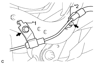
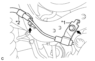
Install the No. 3 bracket and No. 2 bracket to the upper control arm with the 2 bolts.
Table 2. Text in Illustration *1 No. 2 Bracket *2 No. 3 Bracket 8.0 N*m 82 kgf*cm 71 in.*lbf -
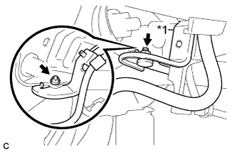
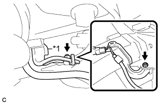
Install the No. 4 bracket to the rear member assembly with the nut.
Table 3. Text in Illustration *1 No. 4 Bracket 9.0 N*m 92 kgf*cm 80 in.*lbf -
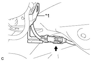
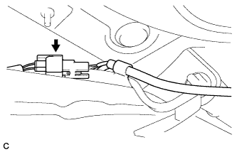
Connect the rear speed sensor connector.
Table 4. Text in Illustration *1 No. 4 Bracket
-
- Click here
INSTALL REAR SPEED SENSOR RH
-
Install the No. 1 bracket and rear speed sensor to the rear trailing arm assembly and the rear axle carrier sub-assembly with the 2 bolts.
Table 5. Text in Illustration *1 No. 1 Bracket *2 Bolt A *3 Bolt B Bolt A 8.5 N*m 87 kgf*cm 75 in.*lbf Bolt B 8.0 N*m 82 kgf*cm 71 in.*lbf Note:
-
Prevent foreign matter from attaching to the rear speed sensor tip.
-
Clean the speed sensor installation hole and the contact surfaces every time the rear speed sensor is removed.
-
-
Install the No. 3 bracket and No. 2 bracket to the upper control arm with the 2 bolts.
Table 6. Text in Illustration *1 No. 2 Bracket *2 No. 3 Bracket 8.0 N*m 82 kgf*cm 71 in.*lbf -
Install the No. 4 bracket to the rear member assembly with the nut.
Table 7. Text in Illustration *1 No. 4 Bracket 9.0 N*m 92 kgf*cm 80 in.*lbf -
Connect the rear speed sensor connector.
-
- Click here
INSTALL REAR WHEEL
103 N*m 1050 kgf*cm 76 ft.*lbf - Click here
CONNECT CABLE TO NEGATIVE BATTERY TERMINAL
Note:When disconnecting the cable, some systems need to be initialized after the cable is reconnected (Click here).
- Click here
INSTALL REAR DECK FLOOR BOX
-
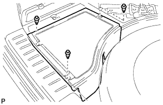
Install the rear deck floor box with the 3 clips.
-
- Click here
CHECK FOR SPEED SENSOR SIGNAL
Tip:(Click here).