BRAKE CONTROL POWER SUPPLY INSTALLATION

Note
While the battery is connected, even if the power switch is off, the brake control system activates when the brake pedal is depressed or any door courtesy switch is turned on. Therefore, when servicing the brake system components, do not depress the brake pedal or open/close the doors while the battery is connected.
-
INSTALL BRAKE CONTROL POWER SUPPLY ASSEMBLY
-
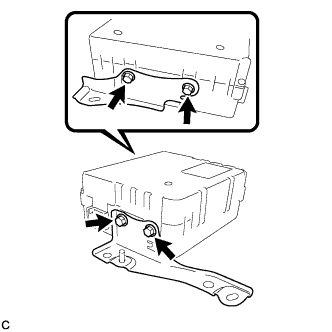
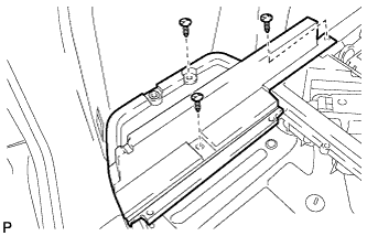
Install the No. 2 control power supply bracket and No. 1 control power supply bracket with the 4 bolts.
- Torque:
- 5.0 N*m { 51 kgf*cm, 44 in.*lbf }
Note
Do not drop the brake control power supply. If the brake control power supply has been dropped, replace the brake control power supply with a new one.
-
-
INSTALL BRAKE CONTROL POWER SUPPLY WITH BRACKET
-
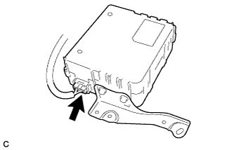
Connect the connector.
-
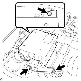
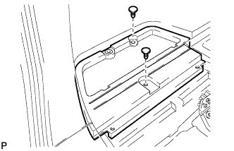
Install the brake control power supply with bracket with the 3 nuts.
- Torque:
- 8.5 N*m { 87 kgf*cm, 75 in.*lbf }
-
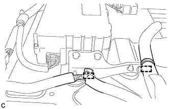
Install the 2 clamps.
-
-
INSTALL REAR FLOOR FINISH PLATE
-
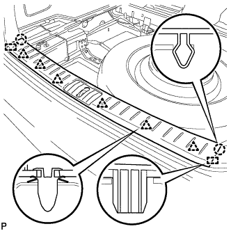
Engage the 6 clips, 2 claws and 2 guides, and install the rear floor finish plate.
-
-
INSTALL FRONT DECK FLOOR BOX
-
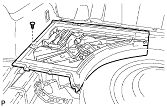
Install the front deck floor box with the clip.
-
-
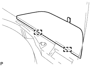
INSTALL DECK SIDE TRIM BOX LH (for Compact Spare Tire)
-
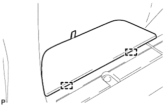
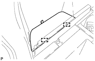
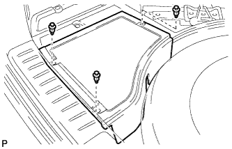
Install the deck side trim box LH with the 2 clips.
-
-
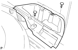
INSTALL DECK SIDE TRIM BOX LH (for Full Size Spare Tire)
-
Install the deck side trim box LH with the 3 clips.
-
-
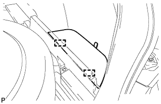
INSTALL DECK SIDE TRIM BOX RH (for Compact Spare Tire)
-
Install the deck side trim box RH with the 2 clips.
-
-
INSTALL DECK SIDE TRIM BOX RH (for Full Size Spare Tire)
-
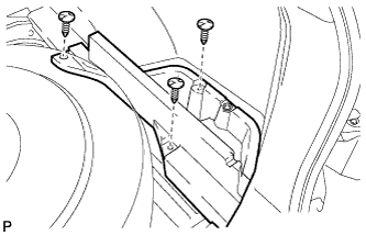
Install the deck side trim box RH with the 3 clips.
-
-
INSTALL TONNEAU COVER ASSEMBLY (w/ Tonneau Cover)
-
Install the tonneau cover assembly.
-
-
INSTALL NO. 3 REAR FLOOR BOARD (for Compact Spare Tire)
-
Engage the 2 guides and install the No. 3 rear floor board.
-
-
INSTALL NO. 3 REAR FLOOR BOARD (for Full Size Spare Tire)
-
Engage the 2 guides and install the No. 3 rear floor board.
-
-
INSTALL NO. 4 REAR FLOOR BOARD (for Compact Spare Tire)
-
Engage the 2 guides and install the No. 4 rear floor board.
-
-
INSTALL NO. 4 REAR FLOOR BOARD (for Full Size Spare Tire)
-
Engage the 2 guides and install the No. 4 rear floor board.
-
-
INSTALL SPARE WHEEL COVER ASSEMBLY
-
Install the spare wheel cover assembly.
-
-
INSTALL DECK BOARD SUB-ASSEMBLY
-
for Compact Spare Tire:
-
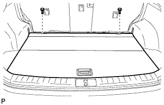
Install the deck board sub-assembly with the 2 bolts.
-
-
for Full Size Spare Tire:
-
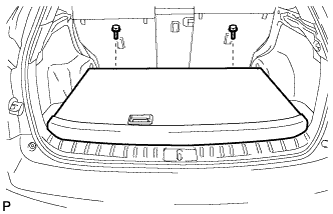
Install the deck board sub-assembly with the 2 bolts.
-
-
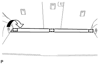
Engage the 3 fasteners as shown in the illustration.
-
-
CONNECT CABLE TO NEGATIVE BATTERY TERMINAL
Note
When disconnecting the cable, some systems need to be initialized after the cable is reconnected Click here.
-
INSTALL REAR DECK FLOOR BOX
-
Install the rear deck floor box with the 3 clips.
-