TIRE PRESSURE WARNING SYSTEM, Diagnostic DTC:C2195/95

| DTC Code | DTC Name |
|---|---|
| C2195/95 | Multi-receiver Antenna Circuit (Test Mode DTC) |
DESCRIPTION
This DTC is used for detecting open circuits and radio wave frequency mismatches in the tire pressure warning antenna.
| DTC No. | DTC Detection Condition | Trouble Area |
|---|---|---|
| C2195/95 | Test mode procedure is performed. |
|
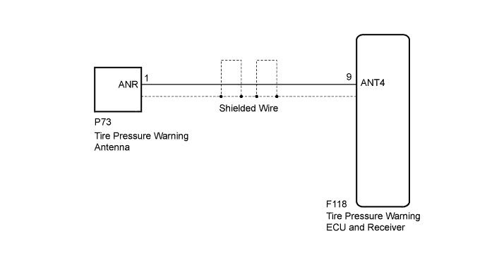
WIRING DIAGRAM
INSPECTION PROCEDURE
Note
-
When replacing the tire pressure warning ECU and receiver, read the transmitter IDs stored in the old ECU using the GTS and write them down before removal.
-
It is necessary to perform initialization Click here after registration Click here of the transmitter IDs into the tire pressure warning ECU and receiver if the ECU has been replaced.
PROCEDURE
-
CHECK HARNESS AND CONNECTOR (TIRE PRESSURE WARNING ECU AND RECEIVER - TIRE PRESSURE WARNING ANTENNA)
-
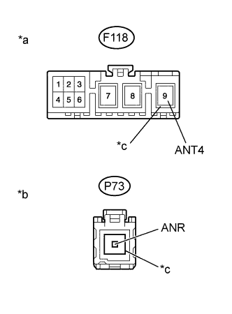
Text in Illustration *a Front view of wire harness connector
(to Tire Pressure Warning ECU and Receiver)
*b Front view of wire harness connector
(to Tire Pressure Warning Antenna)
*c Shielded wire Disconnect the F118 tire pressure warning ECU and receiver connector.
-
Disconnect the P73 tire pressure warning antenna connector.
-
Measure the resistance according to the value(s) in the table below.
Tech Tips
Because the coaxial cable that is used for the tire pressure warning antenna consists of a center conductor and an outer shielding layer (-), this measurement should be performed to ensure that there is no malfunction in the coaxial cable.
Standard Resistance Tester Connection Condition Specified Condition F118-9 (ANT4) - P73-1 (ANR) Always Below 1 Ω F118-9 (shielded wire) - P73-1 (shielded wire) Always Below 1 Ω F118-9 (ANT4) - P73-1 (shielded wire) Always 10 kΩ or higher F118-9 (shielded wire) - P73-1 (ANR) Always 10 kΩ or higher
NG 
REPAIR OR REPLACE HARNESS OR CONNECTOR
OK 
-
-
CHECK TIRE PRESSURE WARNING ANTENNA RECEPTION
-
Set the tire pressure to the specified value Click here.
-
Turn the power switch off.
-
Connect the GTS to the DLC3.
-
Turn the power switch on (IG).
-
Turn the GTS on.
-
Enter the following menus: Chassis / Tire Pressure Monitor / Data List.
-
Check the values by referring to the table below.
Tire Pressure Monitor Tester Display Measurement Item/Range Normal Condition Diagnostic Note ID 1 Tire Inflation Pressure ID1 tire inflation pressure/
min.: Absolute pressure (abs) / 0 kPa (0 kgf/cm2, 0 psi), Relative pressure (Gauge) / 0 kPa (0 kgf/cm2, 0 psi)
max.: Absolute pressure (abs) / 480 kPa (4.9 kgf/cm2, 70 psi), Relative pressure (Gauge) / 380 kPa (3.9 kgf/cm2, 55 psi)
Actual tire inflation pressure If N/A is displayed, data has not been received.*1 ID 2 Tire Inflation Pressure ID2 tire inflation pressure/
min.: Absolute pressure (abs) / 0 kPa (0 kgf/cm2, 0 psi), Relative pressure (Gauge) / 0 kPa (0 kgf/cm2, 0 psi)
max.: Absolute pressure (abs) / 480 kPa (4.9 kgf/cm2, 70 psi), Relative pressure (Gauge) / 380 kPa (3.9 kgf/cm2, 55 psi)
Actual tire inflation pressure If N/A is displayed, data has not been received.*1 ID 3 Tire Inflation Pressure ID3 tire inflation pressure/
min.: Absolute pressure (abs) / 0 kPa (0 kgf/cm2, 0 psi), Relative pressure (Gauge) / 0 kPa (0 kgf/cm2, 0 psi)
max.: Absolute pressure (abs) / 480 kPa (4.9 kgf/cm2, 70 psi), Relative pressure (Gauge) / 380 kPa (3.9 kgf/cm2, 55 psi)
Actual tire inflation pressure If N/A is displayed, data has not been received.*1 ID 4 Tire Inflation Pressure ID4 tire inflation pressure/
min.: Absolute pressure (abs) / 0 kPa (0 kgf/cm2, 0 psi), Relative pressure (Gauge) / 0 kPa (0 kgf/cm2, 0 psi)
max.: Absolute pressure (abs) / 480 kPa (4.9 kgf/cm2, 70 psi), Relative pressure (Gauge) / 380 kPa (3.9 kgf/cm2, 55 psi)
Actual tire inflation pressure If N/A is displayed, data has not been received.*1 ID 5 Tire Inflation Pressure*2 ID5 tire inflation pressure/
min.: Absolute pressure (abs) / 0 kPa (0 kgf/cm2, 0 psi), Relative pressure (Gauge) / 0 kPa (0 kgf/cm2, 0 psi)
max.: Absolute pressure (abs) / 480 kPa (4.9 kgf/cm2, 70 psi), Relative pressure (Gauge) / 380 kPa (3.9 kgf/cm2, 55 psi)
Actual tire inflation pressure*2 If N/A is displayed, data has not been received.*1 Tech Tips
-
*1: It may take a few minutes until the values are displayed.
-
*2: w/ Spare Tire
-
-
Rapidly reduce the tire pressure for each wheel at least 40 kPa (0.4 kgf/cm2, 5.8 psi) within 30 seconds.
-
Check that each "ID Tire Inflation Pressure" value displayed on the GTS has changed.
Result Result Proceed to Tire pressure data does not change A Tire pressure of at least 1 wheel changes B
-
B 
CHECK TEST MODE DTC (C2195/95) Click here
A
-
-
REPLACE TIRE PRESSURE WARNING ANTENNA
-
Replace the tire pressure warning antenna Click here.
NEXT
-
-
CHECK TEST MODE DTC (C2195/95)
-
Turn the power switch off.
-
Connect the GTS to the DLC3.
-
Turn the power switch on (IG).
-
Turn the GTS on.
-
Enter the following menus: Chassis / Tire Pressure Monitor / Utility / Signal Check.
-
Perform the test mode inspection Click here.
Result Result Proceed to DTC C2195/95 is not cleared A DTC C2195/95 is cleared (When performing the test mode inspection after replacing the tire pressure warning antenna) B DTC C2195/95 is cleared (When performing the test mode inspection after the tire pressures have changed as a result of the tire pressure warning antenna reception check) C
B
END
C
USE SIMULATION METHOD TO CHECK Click here
A 
REPLACE TIRE PRESSURE WARNING ECU AND RECEIVER Click here
-