REAR SUSPENSION MEMBER REMOVAL

-
PRECAUTION (w/ Air Suspension)
-
PRECAUTION (w/ Navigation System for HDD)
Note
After the power switch is turned off, the display and navigation module display (HDD navigation system) records various types of memory and settings. As a result, after turning the power switch off, make sure to wait for the time specified in the following table before disconnecting the cable from the negative (-) battery terminal.
Waiting Time before Disconnecting Cable from Negative (-) Battery Terminal Specification Waiting Time w/o Telematics transceiver 60 sec. w/ Telematics transceiver 120 sec. -
REMOVE REAR DECK FLOOR BOX
-
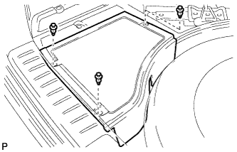
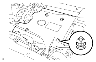
Remove the 3 clips and the rear deck floor box.
-
-
DISCONNECT CABLE FROM NEGATIVE BATTERY TERMINAL
Note
When disconnecting the cable, some systems need to be initialized after the cable is reconnected Click here.
-
REMOVE BATTERY SERVICE HOLE COVER (for AWD)
-
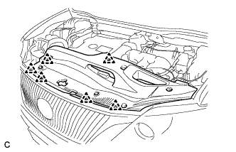
Disengage the 2 clips and 2 guides, and remove the battery service hole cover.
Tech Tips
Because these are 2-piece clips, one side will remain in the bracket when they are being removed.
-
-
REMOVE SERVICE PLUG GRIP (for AWD)
CAUTION:
-
Remove the service plug grip to interrupt a high voltage circuit at the time of the check.
-
Keep the removed service plug grip in your pocket to prevent other technicians from accidentally reconnecting it while you are servicing the vehicle.
-
All the high voltage wiring connectors are orange colored.
-
Wear insulated gloves. Remove the service plug grip after sliding the lever of the service plug grip.
CAUTION:
-
Keep the removed service plug grip in your pocket to prevent other technicians from accidentally reconnecting it while you are servicing the vehicle.
-
After disconnecting the service plug grip, wait for at least 10 minutes before touching any of the high-voltage connectors or terminals.
Tech Tips
Waiting for at least 10 minutes is required to discharge the high-voltage capacitor inside the inverter with converter assembly.
-
-
-
REMOVE ENGINE ROOM SIDE COVER LH (for AWD)
-
Remove the 4 clips and engine room side cover LH.
-
-
REMOVE ENGINE ROOM SIDE COVER (for AWD)
-
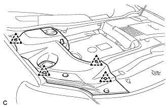
Remove the 4 clips and engine room side cover.
-
-
REMOVE COOL AIR INTAKE DUCT SEAL (for AWD)
-
Remove the 6 clips and cool air intake duct seal.
-
-
REMOVE INTAKE AIR RESONATOR SUB-ASSEMBLY (for AWD)
-
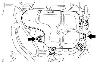
Remove the 3 clamps and Disconnect the water hose from the intake air resonator sub-assembly.
-
Remove the 2 bolts and intake air resonator sub-assembly from the inverter with converter assembly.
-
-
REMOVE INLET NO. 2 AIR CLEANER (for AWD)
-
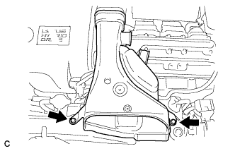
Remove the 2 bolts and inlet No. 2 air cleaner.
-
-
REMOVE INVERTER TERMINAL COVER (for AWD)
CAUTION:
Wear insulating gloves.
-
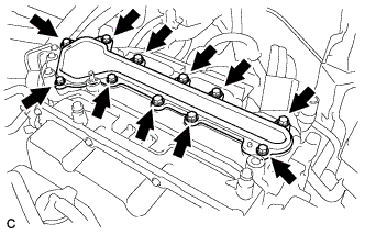
Remove the 11 bolts and inverter terminal cover.
Note
Make sure to pull the inverter cover straight up, as a connector is connected to the bottom of the cover.
-
-
CHECK TERMINAL VOLTAGE (for AWD)
CAUTION:
Wear insulating gloves.
Note
-
Insulate the removed terminals with insulating tape.
-
Do not allow any foreign objects or water to enter the inverter with converter assembly.
-
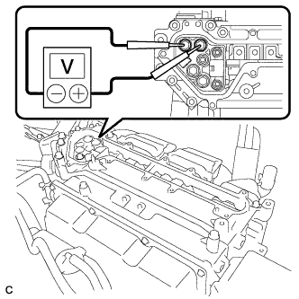
Using a voltmeter, measure the voltage between the 2 terminals.
Standard voltage 0 V Tech Tips
Use a measuring range of DC 750 V or more on the voltmeter.
-
-
INSTALL INVERTER TERMINAL COVER (for AWD)
CAUTION:
Wear insulating gloves.
Note
-
Make sure that the interlock are fully engaged.
-
Do not allow any foreign objects or water to enter the inverter with converter assembly.
-
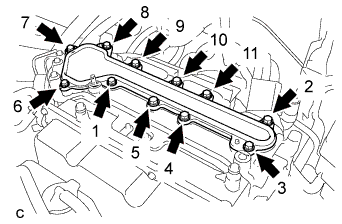
Using several steps, install the inverter terminal cover with the 11 bolts uniformly in the sequence shown in the illustration.
- Torque:
- 8.0 N*m { 82 kgf*cm, 71 in.*lbf }
-
-
INSTALL INLET NO. 2 AIR CLEANER (for AWD)
-
Install the inlet No. 2 air cleaner with the 2 bolts.
- Torque:
- 8.0 N*m { 82 kgf*cm, 71 in.*lbf }
-
-
INSTALL INTAKE AIR RESONATOR SUB-ASSEMBLY (for AWD)
-
Install the intake air resonator sub-assembly with the 2 bolts.
- Torque:
- 8.0 N*m { 82 kgf*cm, 71 in.*lbf }
-
Connect the 3 water hose clamps to the intake air resonator sub-assembly.
-
-
REMOVE V-BANK COVER SUB-ASSEMBLY (w/ Exhaust Heat Recirculation System)
-
Hold the front of the V-bank cover sub-assembly and raise it to disengage the 2 retainers on the front of the V-bank cover sub-assembly. Continue to raise the V-bank cover sub-assembly to disengage the 2 retainers on the rear of the V-bank cover sub-assembly and remove the V-bank cover sub-assembly.
Note
Attempting to disengage both front and rear retainers at the same time may cause the V-bank cover sub-assembly to break.
-
-
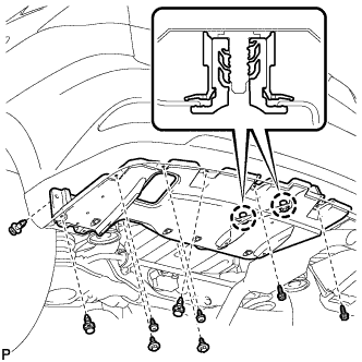
REMOVE NO.1 ENGINE UNDER COVER (w/ Exhaust Heat Recirculation System)
-
DRAIN ENGINE COOLANT (for Engine with Exhaust Heat Recirculation System)
Note
Do not remove the radiator cap, cylinder block drain cock plugs and radiator drain cock plug while the engine and radiator are still hot. Pressurized hot engine coolant and steam may be released and cause serious burns.
-
Loosen the radiator drain cock plug and drain the coolant.
Tech Tips
Collect the coolant in a container and dispose of it according to the regulations in your area.
-
Remove the radiator cap from the radiator assembly.
-
Loosen the 2 cylinder block drain cock plugs.
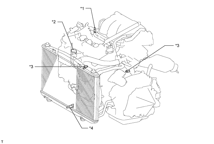
Text in Illustration *1 Air Drain Cock Plug *2 Radiator Cap *3 Cylinder Block Drain Cock Plug *4 Radiator Drain Cock Plug
-
-
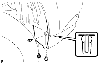
REMOVE FRONT FLOOR COVER LH (w/ Exhaust Heat Recirculation System)
-
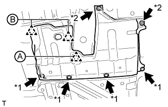
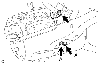
Text in Illustration *1 Bolt *2 Screw Remove the clip (A).
-
Disconnect the 2 clips (B).
-
Remove the 2 screws, 4 bolts and front floor cover LH.
-
-
REMOVE REAR WHEELS
-
REMOVE TAIL EXHAUST PIPE ASSEMBLY
-
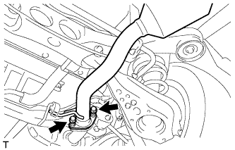
Remove the 2 bolts and 2 compression springs.
-
Remove the tail exhaust pipe assembly from the 2 exhaust pipe supports.
-
Remove the gasket from the center exhaust pipe assembly.
-
-
REMOVE HEATER COVER (w/ Exhaust Heat Recirculation System)
-
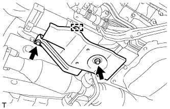
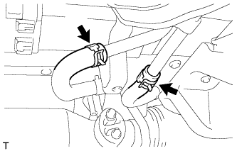
Disconnect the clamp.
-
Remove the 2 bolts and heater cover.
-
-
REMOVE CENTER EXHAUST PIPE ASSEMBLY (w/ Exhaust Heat Recirculation System)
Note
When removing or installing the center exhaust pipe assembly, do not subject the temperature switch to impacts.
-
Disconnect the 2 heater water hoses.
-
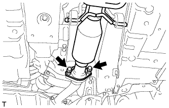
Remove the 2 bolts and 2 compression springs.
-
Remove the center exhaust pipe assembly from the 4 exhaust pipe supports.
-
Remove the gasket from the front No. 3 exhaust pipe sub-assembly.
-
-
REMOVE CENTER EXHAUST PIPE ASSEMBLY (w/o Exhaust Heat Recirculation System)
-
Remove the 2 bolts and 2 compression springs.
-
Remove the center exhaust pipe assembly from the 4 exhaust pipe supports.
-
Remove the gasket from the front No. 3 exhaust pipe sub-assembly.
-
-
SEPARATE REAR SPEED SENSOR WIRE RH (for 2WD)
-
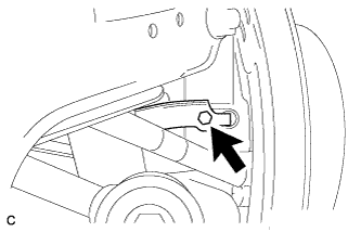
Remove the bolt and No. 1 bracket.
-
Using a screwdriver, disconnect the connector from the rear speed sensor.
Note
Be careful not to damage the rear speed sensor.
-
-
SEPARATE REAR SPEED SENSOR WIRE LH (for 2WD)
Tech Tips
Perform the same procedure as the LH side.
-
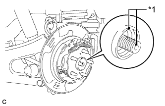
SEPARATE REAR SPEED SENSOR LH (for AWD)
-

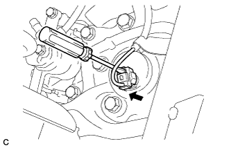
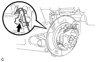
Remove the bolt and separate the rear speed sensor from the rear axle carrier sub-assembly.
Note
-
Prevent foreign matter from attaching to the rear speed sensor tip.
-
Clean the rear speed sensor installation hole and the contact surfaces every time the rear speed sensor is removed.
-
Do not twist or apply excessive force to the rear speed sensor during removal from the rear axle carrier sub-assembly to prevent it from being damaged.
-
-
Remove the bolt and separate the rear speed sensor from the rear trailing arm assembly.
-
-
SEPARATE REAR SPEED SENSOR RH (for AWD)
Tech Tips
Perform the same procedure as the LH side.
-
REMOVE REAR AXLE SHAFT NUT LH (for AWD)
-
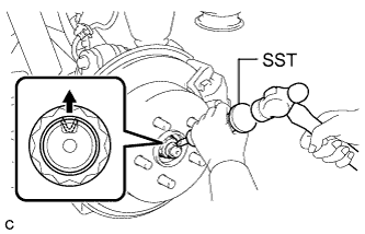
Using SST and a hammer, release the staked part of the rear axle shaft nut.
- SST
- 09930-00010
Note
Loosen the staked part of the nut completely, otherwise the threads of the rear drive shaft assembly may be damaged.
-

While applying the parking brakes, remove the rear axle shaft nut from the rear drive shaft assembly.
-
-
REMOVE REAR AXLE SHAFT NUT RH (for AWD)
Tech Tips
Perform the same procedure as the LH side.
-
REMOVE REAR SUSPENSION ARM COVER LH
w/o Air Suspension: Click here
w/ Air Suspension: Click here
-
REMOVE REAR SUSPENSION ARM COVER RH
Tech Tips
Perform the same procedure as the LH side.
-
REMOVE REAR DRIVE SHAFT ASSEMBLY LH (for AWD)
-
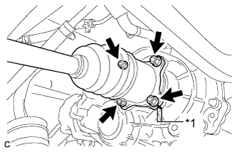
Text in Illustration *1 Matchmark Put matchmarks on the rear drive shaft assembly and differential side gear shaft.
-
Remove the 4 nuts, washers and rear drive shaft assembly.
-
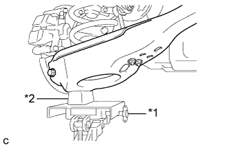
Text in Illustration *1 Jack *2 Wooden Block Using a jack and wooden block, jack up the rear No. 2 suspension arm assembly to replicate standard vehicle height conditions.
Note
Do not jack up the rear No. 2 suspension arm assembly too high as the vehicle may fall.
-
Text in Illustration *1 Matchmark Put matchmarks on the rear drive shaft assembly and rear axle hub and bearing assembly.
-
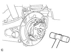
Using a plastic hammer, separate the rear drive shaft assembly from the rear axle hub and bearing assembly.
Tech Tips
If it is difficult to separate, tap the end of the rear drive shaft assembly using a brass bar and a hammer.
-
Push the rear drive shaft inboard joint assembly toward the outside of the vehicle and remove the rear drive shaft assembly LH from the differential side gear shaft sub-assembly.
-
-
REMOVE REAR DRIVE SHAFT ASSEMBLY RH (for AWD)
Tech Tips
Perform the same procedure as the LH side.
-
DRAIN BRAKE FLUID
Note
If brake fluid leaks onto any painted surface, immediately wash it off.
-
SEPARATE REAR FLEXIBLE HOSE LH
-
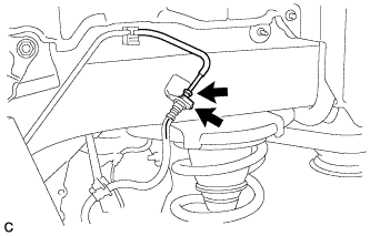
Using a union nut wrench, disconnect the brake line from the rear flexible hose LH.
Note
-
Do not bend or damage the brake line.
-
Do not allow any foreign matter such as dirt and dust to enter the brake line.
-
-
Remove the clip and separate the rear flexible hose LH.
-
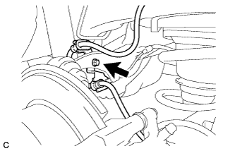
Remove the bolt and separate the rear flexible hose LH from the rear upper control arm assembly LH.
-
-
SEPARATE REAR FLEXIBLE HOSE RH
Tech Tips
Perform the same procedure as the LH side.
-
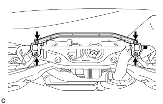
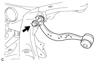
REMOVE REAR STABILIZER LINK SUB-ASSEMBLY (for LH Side)
-
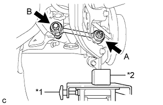
Remove the 2 nuts (A) and rear stabilizer link sub-assembly from the rear No. 2 suspension arm assembly.
-
Remove the nut (B) and separate the rear stabilizer link sub-assembly from the rear stabilizer bar.
Tech Tips
If the ball joint turns together with the nut (B), use a hexagon wrench (6 mm) to hold the stud bolt.
-
-
REMOVE REAR STABILIZER LINK SUB-ASSEMBLY (for RH Side)
Tech Tips
Perform the same procedure as the LH side.
-
REMOVE REAR QUARTER PANEL MUDGUARD SUB-ASSEMBLY LH (w/ Active Stabilizer System)
Tech Tips
This step is not necessary for vehicles without the rear fender mudguard.
-
REMOVE NO. 2 LUGGAGE COMPARTMENT SIDE COVER PROTECTOR (w/ Active Stabilizer System)
-
Remove the 2 screws and grommet.
-
Remove the 4 screws.
-
Remove the 2 bolts and 3 clips.
-
Disengage the 2 claws and remove the No. 2 luggage compartment side cover protector.
-
-
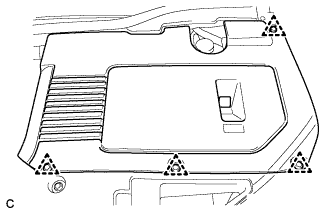
REMOVE REAR STABILIZER BAR (w/o Active Stabilizer System)
-
Type A:
-
Remove the 4 nuts and rear stabilizer bar with 2 rear stabilizer bushings and rear No. 1 stabilizer bar bracket.
-
-
Type B:
-
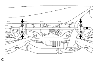
Remove the 4 nuts and rear stabilizer bar with 2 rear stabilizer bushings and 2 rear No. 1 stabilizer bar brackets.
-
-
-
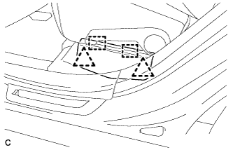
REMOVE REAR ACTIVE STABILIZER CONTROL ACTUATOR ASSEMBLY (w/ Active Stabilizer System)
-
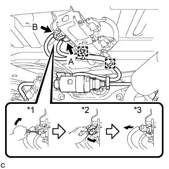
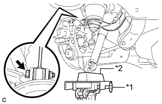
Disengage the 2 clamps and disconnect the connector (A).
-
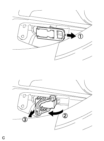
Using the procedures below, disconnect the connector (B).
-
Using a screwdriver, release the lever's lock.*1
-
Move the lever in the direction of the arrow in the illustration.*2
-
Disconnect the ECU connector.*3
Note
When disconnecting the connector, do not apply excessive force to the wire harness.
-
-
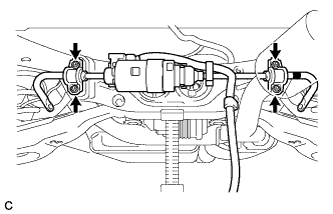
Type A:
-
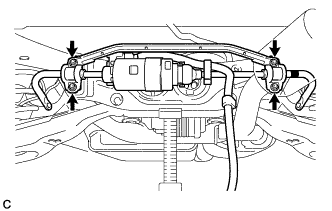
Remove the 4 nuts and rear active stabilizer control actuator assembly with 2 rear stabilizer bushings and rear No. 1 stabilizer bar bracket.
Note
-
Take care not to damage the wire harness and connectors of the rear active stabilizer control actuator assembly.
-
Avoid any impact to the rear active stabilizer control actuator assembly.
-
Do not drop the rear active stabilizer control actuator assembly. If it is dropped, replace it with a new one.
-
-
-
Type B:
-
Remove the 4 nuts and rear active stabilizer control actuator assembly with 2 rear stabilizer bushings and 2 rear No. 1 stabilizer bar brackets.
Note
-
Take care not to damage the wire harness and connectors of the rear active stabilizer control actuator assembly.
-
Avoid any impact to the rear active stabilizer control actuator assembly.
-
Do not drop the rear active stabilizer control actuator assembly. If it is dropped, replace it with a new one.
-
-
-
-
REMOVE REAR PNEUMATIC CYLINDER ASSEMBLY LH (w/ Air Suspension)
-
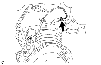
Disconnect the air tube from the rear pneumatic cylinder assembly.
Tech Tips
For the disconnecting procedure of the tube (type 2), refer to Precaution of the suspension control system Click here.
-
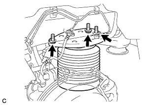
Remove the 3 bolts and separate the rear pneumatic cylinder assembly from the body.
-
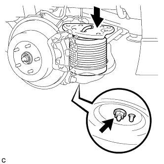
Compress the rear pneumatic cylinder assembly as shown in the illustration.
-
Remove the nut and rear pneumatic cylinder assembly from the rear No. 2 suspension arm assembly.
Note
-
Hold the lower part of the rear pneumatic cylinder assembly when removing it.
-
Do not extend the rear pneumatic cylinder assembly when removing it.
-
-
Remove the 2 O-rings, plate and No. 2 connector from the rear pneumatic cylinder assembly.
Note
Perform this procedure when reusing the rear pneumatic cylinder assembly.
Tech Tips
For the removing procedure of the tube (type 2), refer to Precaution of the suspension control system Click here.
-
-
REMOVE REAR PNEUMATIC CYLINDER ASSEMBLY RH (w/ Air Suspension)
Tech Tips
Perform the same procedure as the LH side.
-
REMOVE REAR NO. 2 SUSPENSION ARM ASSEMBLY LH
w/o Air Suspension: Click here
w/ Air Suspension: Click here
-
REMOVE REAR NO. 2 SUSPENSION ARM ASSEMBLY RH
Tech Tips
Perform the same procedure as the LH side.
-
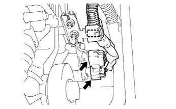
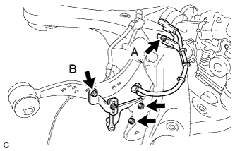
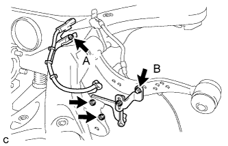
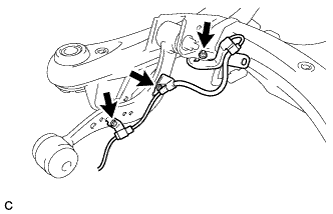
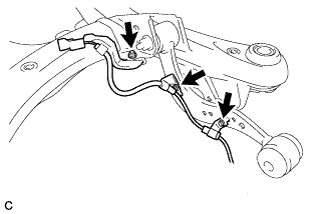
SEPARATE FRAME WIRE
-
Remove the bolt and disconnect the connectors, and then disengage the clamps to separate the frame wire from the rear suspension member sub-assembly as shown in the illustration.
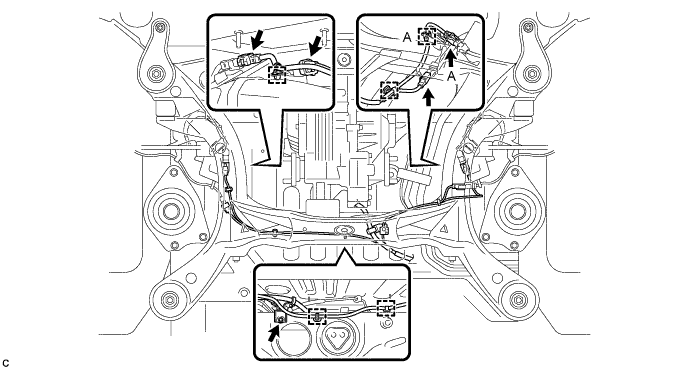
Tech Tips
-
There are only the connector (A) and the clamp (A) on vehicles with the air suspension.
-
Use the same procedure for the 2WD and AWD.
-
-
-
SEPARATE NO. 3 WIRE FRAME (for AWD)
Note
Wear insulated gloves.
-
Disconnect the 2 connectors and clamp.
-
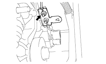
Remove the nut, and separate the ground cable.
-
Remove the nut, and separate the wire harness clamp.
-
Wear the insulated gloves. Remove the 2 nuts, and separate the No. 3 wire frame from the rear traction with transaxle motor.
-
-
REMOVE REAR SUSPENSION MEMBER SUB-ASSEMBLY
Tech Tips
-
Use the same procedure for the 2WD and AWD.
-
The procedure listed below is for the AWD.
-
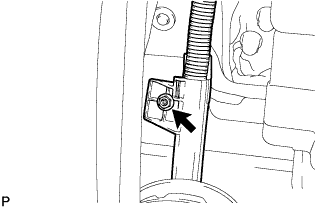
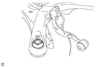
Separate the rear upper control arm assembly LH.
-
Text in Illustration *1 Jack *2 Wooden Block Using a jack and wooden block, jack up the rear axle assembly LH to replicate standard vehicle height conditions.
-
Remove the bolt and nut, and then separate the rear upper control arm assembly LH from the rear axle carrier sub-assembly LH.
Note
Since the stopper nut is used, loosen the bolt.
-
Slowly lower the rear axle assembly LH.
-
-
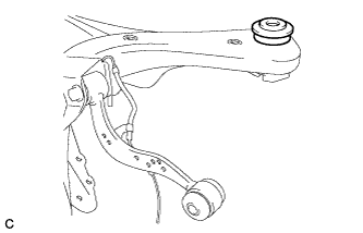
Separate the rear upper control arm assembly RH.
Tech Tips
Perform the same procedure as the LH side.
-
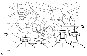
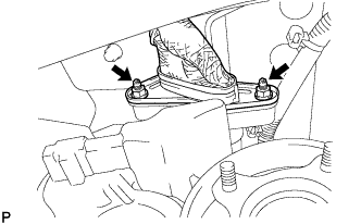
Text in Illustration *1 Jack *2 Attachment Support the rear suspension member sub-assembly with a jack using 4 attachments or equivalent tools as shown in the illustration.
Note
Make sure to secure the rear suspension member sub-assembly to prevent it from dropping.
-
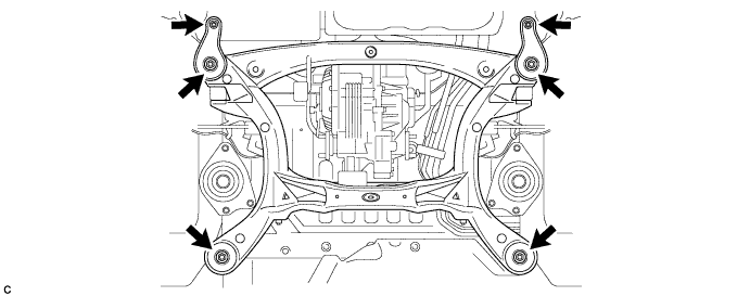
Remove the 2 nuts, 4 bolts, 2 rear lower suspension braces and 2 rear lower suspension member stoppers.
-
Remove the rear No. 1 suspension arm assembly LH.
-
Text in Illustration *1 Jack *2 Wooden Block Using a jack and wooden block, jack up the rear axle assembly LH to replicate standard vehicle height conditions.
-
Remove the nut (A) and the spacer.
-
Remove the bolt (B), nut and rear No. 1 suspension arm assembly LH.
Note
Since the stopper nut is used, loosen the bolt (B).
-
Slowly lower the rear axle assembly LH.
-
-
Remove the rear No. 1 suspension arm assembly RH.
Tech Tips
Perform the same procedure as the LH side.
-
Slowly lower the rear suspension member sub-assembly.
Note
When lowering the rear suspension member sub-assembly, be careful not to damage the vehicle body or other components installed on the vehicle.
-
-
REMOVE REAR SUSPENSION MEMBER UPPER STOPPER
-
Remove the 2 rear suspension member upper stoppers.
-
-
REMOVE REAR SUSPENSION MEMBER REAR UPPER STOPPER
-
Remove the 2 rear suspension member rear upper stoppers.
-
-
REMOVE REAR HEIGHT CONTROL SENSOR SUB-ASSEMBLY RH (w/ HID, LED Headlight System)
-
Remove the bolt (B) and separate the rear height control sensor sub-assembly RH from the rear upper control arm assembly RH.
-
Remove the bolt (A), 2 nuts and rear height control sensor sub-assembly RH from the rear suspension member sub-assembly.
-
-
REMOVE REAR HEIGHT CONTROL SENSOR SUB-ASSEMBLY LH (w/ Air Suspension)
-
Remove the bolt (B) and separate the rear height control sensor sub-assembly LH from the rear upper control arm assembly LH.
-
Remove the bolt (A), 2 nuts and rear height control sensor sub-assembly LH from the rear suspension member sub-assembly.
-
-
REMOVE REAR SPEED SENSOR WIRE LH (for 2WD)
-
Remove the 2 bolts, nut and rear speed sensor wire LH.
-
-
REMOVE REAR SPEED SENSOR LH (for AWD)
Tech Tips
Perform the same procedure as the rear speed sensor wire LH.
-
REMOVE REAR SPEED SENSOR WIRE RH (for 2WD)
-
Remove the 2 bolts, nut and rear speed sensor wire RH.
-
-
REMOVE REAR SPEED SENSOR RH (for AWD)
Tech Tips
Perform the same procedure as the rear speed sensor wire RH.
-
REMOVE REAR UPPER CONTROL ARM ASSEMBLY LH
-
Remove the bolt, nut and rear upper control arm assembly LH from the rear suspension member sub-assembly.
Note
Since the stopper nut is used, loosen the bolt.
-
-
REMOVE REAR UPPER CONTROL ARM ASSEMBLY RH
Tech Tips
Perform the same procedure as the LH side.
-
REMOVE REAR TRACTION WITH TRANSAXLE MOTOR ASSEMBLY (for AWD)
-
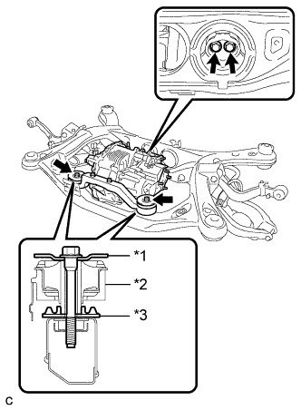
Text in Illustration *1 Upper Differential Mount Support *2 Front Differential Support Assembly *3 Lower Differential Mount Support Remove the 4 bolts and rear traction with transaxle motor assembly.
-
-
REMOVE DIFFERENTIAL MOUNT CUSHION (for AWD)
-
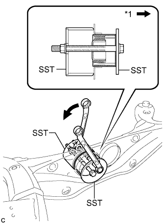
Text in Illustration *1 Front of the Vehicle Using SST, remove the differential mount cushion from the rear suspension member sub-assembly.
- SST
- 09570-48010
Note
-
Before using SST, apply grease to the SST bolts.
-
Install the SST bolts straight and tighten them equally.
-
-
REMOVE REAR SUSPENSION MEMBER FRONT BODY MOUNTING CUSHION (for LH Side)
-
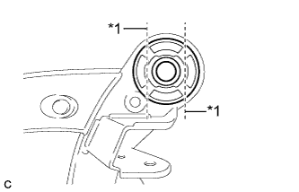
Text in Illustration *1 Bend Portion Using a chisel and hammer, bend the 2 portions of the rear suspension member front body mounting cushion rib.
Note
Make sure to bend the 2 portions of the cushion rib until the claws of SST can fit securely.
-
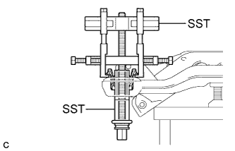
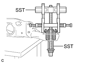
Install SST as shown in the illustration.
- SST
- 09830-10010 ( 09830-01010, 09830-01040, 09830-01050 )
- 09950-40011 ( 09951-04020, 09952-04010, 09954-04010, 09955-04051, 09958-04011 )
Note
Before using SST, apply grease to the SST bolts.
-
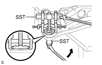
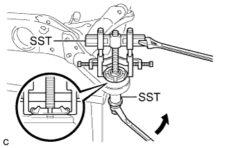
Using SST, separate the rear suspension member front body mounting cushion (LH side) from the rear suspension member sub-assembly, while applying grease to the clearance between the rear suspension member front body mounting cushion (LH side) and the rear suspension member sub-assembly.
- SST
- 09830-10010 ( 09830-01010, 09830-01040, 09830-01050 )
- 09950-40011 ( 09951-04020, 09952-04010, 09954-04010, 09955-04051, 09958-04011 )
Note
-
Set the claws of SST onto the rear suspension member sub-assembly securely as shown in the illustration.
-
Be careful as the rear suspension member front body mounting cushion may fly out.
-
The rear suspension member front body mounting cushion cannot be reused.
-
Remove SST and the rear suspension member front body mounting cushion (LH side) from the rear suspension member sub-assembly.
-
-
REMOVE REAR SUSPENSION MEMBER FRONT BODY MOUNTING CUSHION (for RH Side)
Tech Tips
Perform the same procedure as the LH side.
-
REMOVE REAR SUSPENSION MEMBER REAR BODY MOUNT CUSHION LH
-
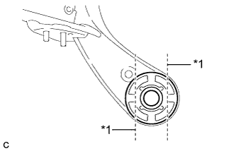
Text in Illustration *1 Bend Portion Using a chisel and hammer, bend the 2 portions of the rear suspension member rear body mounting cushion LH rib.
Note
Make sure to bend the 2 portions of the cushion rib until the claws of SST can fit securely.
-
Install SST as shown in the illustration.
- SST
- 09830-10010 ( 09830-01010, 09830-01040, 09830-01050 )
- 09950-40011 ( 09951-04020, 09952-04010, 09954-04010, 09955-04051, 09958-04011 )
Note
Before using SST, apply grease to the SST bolts.
-
Using SST, separate the rear suspension member rear body mounting cushion LH from the rear suspension member sub-assembly, while applying grease to the clearance between the rear suspension member rear body mounting cushion LH and the rear suspension member sub-assembly.
- SST
- 09830-10010 ( 09830-01010, 09830-01040, 09830-01050 )
- 09950-40011 ( 09951-04020, 09952-04010, 09954-04010, 09955-04051, 09958-04011 )
Note
-
Set the claws of SST onto the rear suspension member sub-assembly securely as shown in the illustration.
-
Be careful as the rear suspension member rear body mounting cushion may fly out.
-
The rear suspension member rear body mounting cushion cannot be reused.
-
Remove SST and the rear suspension member rear body mounting cushion LH from the rear suspension member sub-assembly.
-
-
REMOVE REAR SUSPENSION MEMBER REAR BODY MOUNT CUSHION RH
Tech Tips
Perform the same procedure as the LH side.
-
REMOVE BOLT (for 2WD)
-
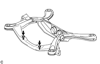
Remove the 2 bolts from the rear suspension member sub-assembly as shown in the illustration.
-
-
REMOVE HOLE PLUG
-
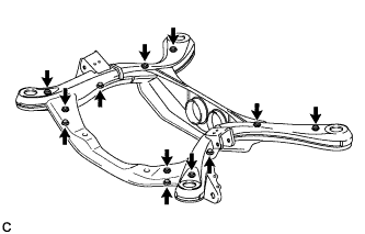
Remove the 12 hole plugs from the rear suspension member sub-assembly as shown in the illustration.
-