REAR ACTIVE STABILIZER CONTROL ACTUATOR REMOVAL

-
REMOVE REAR STABILIZER LINK SUB-ASSEMBLY
-
Remove the rear stabilizer link sub-assembly (LH Side).
-
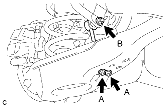
Remove the 2 nuts (A) and separate the rear stabilizer link sub-assembly from the rear No. 2 suspension arm assembly LH.
-
Remove the nut (B) and separate the rear stabilizer link sub-assembly with rear lower stabilizer bracket.
Tech Tips
If the ball joint turns together with the nut, use a hexagon wrench (6 mm) to hold the stud bolt.
-
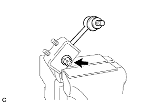
Hold the rear lower stabilizer bracket between aluminium plates in a vise as shown in the illustration.
Note
Do not overtighten the vise.
-
Remove the nut and rear stabilizer link sub-assembly from the rear lower stabilizer bracket.
Tech Tips
If the ball joint turns together with the nut, use a hexagon wrench (6 mm) to hold the stud bolt.
-
-
Remove the rear stabilizer link sub-assembly (RH Side).
Tech Tips
Perform the same procedure as the LH side.
-
-
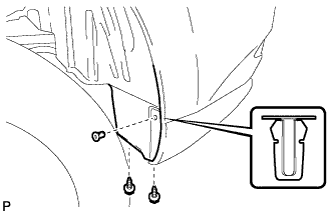
REMOVE REAR QUARTER PANEL MUDGUARD SUB-ASSEMBLY LH (w/ Rear Fender Mudguard)
-
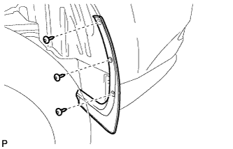
Using a 4 mm hexagon wrench, remove the 3 hexagon screws.
-
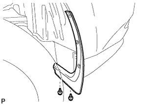
Remove the 2 screws and rear quarter panel mudguard sub-assembly.
-
-
REMOVE NO. 2 LUGGAGE COMPARTMENT SIDE COVER PROTECTOR
-
Remove the 2 screws and grommet.
-
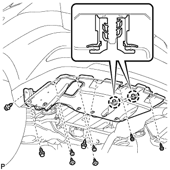
Remove the 4 screws.
-
Remove the 2 bolts and 3 clips.
-
Disengage the 2 claws and remove the No. 2 luggage compartment side cover protector.
-
-
REMOVE REAR ACTIVE STABILIZER CONTROL ACTUATOR ASSEMBLY
-
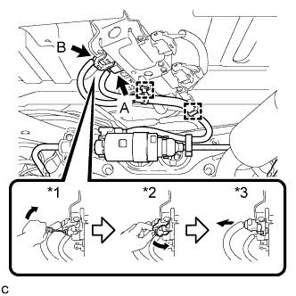
Disengage the 2 clamps and disconnect the connector (A).
-
Using the procedures below, disconnect the connector (B).
-
Using a screwdriver, release the lever's lock.*1
-
Move the lever in the direction of the arrow in the illustration.*2
-
Disconnect the ECU connector.*3
Note
When disconnecting the connector, do not apply excessive force to the wire harness.
-
-
Type A:
-
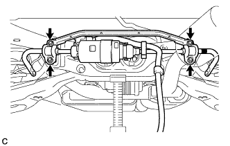
Remove the 4 nuts and rear active stabilizer control actuator assembly with 2 rear stabilizer bushings and rear No. 1 stabilizer bar bracket.
Note
-
Take care not to damage the wire harness and connectors of the rear active stabilizer control actuator assembly.
-
Avoid any impact to the rear active stabilizer control actuator assembly.
-
Do not drop the rear active stabilizer control actuator assembly. If it is dropped, replace it with a new one.
-
-
-
Type B:
-
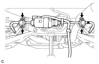
Remove the 4 nuts and rear active stabilizer control actuator assembly with 2 rear stabilizer bushings and 2 rear No. 1 stabilizer bar brackets.
Note
-
Take care not to damage the wire harness and connectors of the rear active stabilizer control actuator assembly.
-
Avoid any impact to the rear active stabilizer control actuator assembly.
-
Do not drop the rear active stabilizer control actuator assembly. If it is dropped, replace it with a new one.
-
-
-
-
REMOVE REAR NO. 1 STABILIZER BAR BRACKET
-
Type A:
-
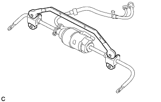
Remove the rear No. 1 stabilizer bar bracket from the 2 rear stabilizer bushings.
-
-
Type B:
-
Remove the 2 rear No. 1 stabilizer bar brackets from the 2 rear stabilizer bushings.
-
-
-
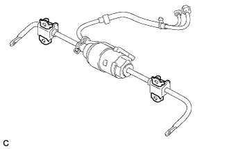
REMOVE REAR STABILIZER BUSHING
-

Remove the 2 rear stabilizer bushings from the rear active stabilizer control actuator assembly.
-