FRONT ACTIVE STABILIZER CONTROL ACTUATOR INSTALLATION

-
INSTALL FRONT NO. 1 STABILIZER BAR BUSHING
-
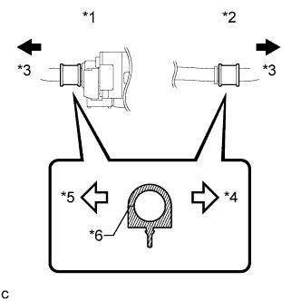
Text in Illustration *1 LH Side *2 RH Side *3 Outside of the Vehicle *4 Front of the Vehicle *5 Rear of the Vehicle *6 Cutout Install the 2 front No. 1 stabilizer bar bushings to the front active stabilizer control actuator assembly as shown in the illustration.
Note
When installing the front No. 1 stabilizer bar bushings, make sure that the cutout faces the rear of the vehicle.
-
-
INSTALL FRONT NO. 2 STABILIZER BRACKET LH
-
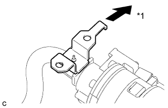
Text in Illustration *1 Rear of the Vehicle Install the front No. 2 stabilizer bracket LH to the front active stabilizer control actuator assembly.
Note
Make sure that the longer side of the front No. 2 stabilizer bracket LH is facing the rear of the vehicle as shown in the illustration.
-
-
INSTALL FRONT NO. 2 STABILIZER BRACKET RH
Tech Tips
Perform the same procedure as for the LH side.
-
INSTALL FRONT ACTIVE STABILIZER CONTROL ACTUATOR ASSEMBLY
-
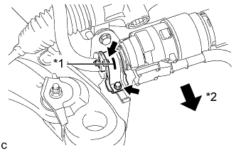
Install the front active stabilizer control actuator assembly to the front frame assembly.
Note
-
Take care not to damage the front active stabilizer control actuator assembly wire harness.
-
Avoid any impact to the front active stabilizer control actuator assembly.
-
Do not drop the front active stabilizer control actuator assembly. If it is dropped, replace it with a new one.
-
-
-
INSTALL FRONT NO. 1 STABILIZER BRACKET LH
-
Text in Illustration *1 Paint Mark *2 Rear of the Vehicle Install the front No. 1 stabilizer bracket LH to the front frame assembly with the 2 bolts.
- Torque:
- 29 N*m { 296 kgf*cm, 21 ft.*lbf }
Note
Make sure to install the front No. 1 stabilizer bracket LH with the paint mark facing rearward.
-
-
INSTALL FRONT NO. 1 STABILIZER BRACKET RH
Tech Tips
Perform the same procedure as for the LH side.
-
INSTALL FRONT STABILIZER LINK ASSEMBLY LH
-
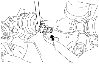
Install the front stabilizer link assembly LH with the nut.
- Torque:
- 74 N*m { 755 kgf*cm, 55 ft.*lbf }
Tech Tips
If the ball joint turns together with the nut, use a hexagon wrench (6 mm) to hold the stud bolt.
-
-
INSTALL FRONT STABILIZER LINK ASSEMBLY RH
Tech Tips
Perform the same procedure as for the LH side.
-
INSTALL ENGINE ASSEMBLY WITH TRANSAXLE
Tech Tips
Refer to the procedure from Install Engine Assembly with Transaxle Click here.