CONTROL VALVE ASSEMBLY (for Front Side) INSTALLATION

-
INSTALL NO. 1 HEIGHT CONTROL VALVE SUB-ASSEMBLY
-
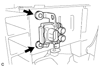
Install the No. 1 height control valve sub-assembly with the 2 bolts.
- Torque:
- 5.4 N*m { 55 kgf*cm, 48 in.*lbf }
-
Coat 5 new O-rings with MP grease No. 2.
-
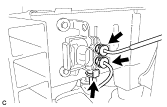
Install the new O-rings and connect the 3 height control tubes onto the No. 1 height control valve sub-assembly.
Tech Tips
For the connecting procedure of the tube (type 3), refer to Precaution of the suspension control system Click here.
-
Lock the 3 holders.
-
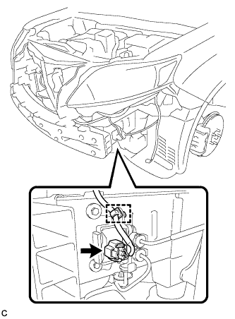
Connect the connector and engage the clamp.
-
-
CONNECT CABLE TO NEGATIVE AUXILIARY BATTERY TERMINAL
Note
When disconnecting the cable, some systems need to be initialized after the cable is reconnected Click here.
-
INSTALL REAR DECK FLOOR BOX
-
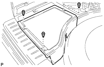
Install the rear deck floor box with the 3 clips.
-
-
INSPECT FOR AIR LEAK
-
Inspect for air leaks Click here.
-
-
INSTALL FRONT BUMPER ASSEMBLY
for Standard: Click here
for Sport Package: Click here
-
PERFORM INITIALIZATION
-
Perform initialization Click here.
-