- Click here
PRECAUTION (w/ Navigation System for HDD)
Note:After the power switch is turned off, the display and navigation module display (HDD navigation system) records various types of memory and settings. As a result, after turning the power switch off, make sure to wait for the time specified in the following table before disconnecting the cable from the negative (-) battery terminal.
Table 1. Waiting Time before Disconnecting Cable from Negative (-) Battery Terminal Specification Waiting Time w/o Telematics transceiver 60 sec. w/ Telematics transceiver 120 sec. - Click here
REMOVE REAR DECK FLOOR BOX
-
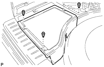
Remove the 3 clips and the rear deck floor box.
-
- Click here
DISCONNECT CABLE FROM NEGATIVE BATTERY TERMINAL
CAUTION:Wait at least 90 seconds after disconnecting the cable from the negative (-) battery terminal to disable the SRS system (Click here).
Note:When disconnecting the cable, some systems need to be initialized after the cable is reconnected (Click here).
- Click here
REMOVE SHIFT LEVER KNOB SUB-ASSEMBLY
-
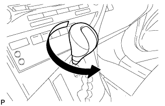
Turn the shift lever knob sub-assembly counterclockwise and remove the shift lever knob sub-assembly.
-
- Click here
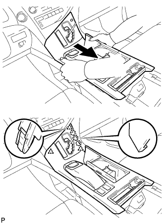
REMOVE UPPER CONSOLE PANEL SUB-ASSEMBLY
-
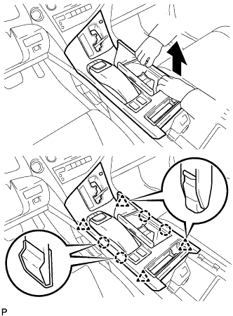
Move the shift lever to N.
-
Pull the upper console panel sub-assembly in the direction indicated by the arrow to disengage the 4 claws and 4 clips.
-
w/o Seat Heater System:
-
Disconnect the connector from the console box hole cover.
-
-
w/ Seat Heater System:
-
Disengage the 6 claws.
-
Disconnect the connector and remove the seat heater switch with console box hole cover.
-
-
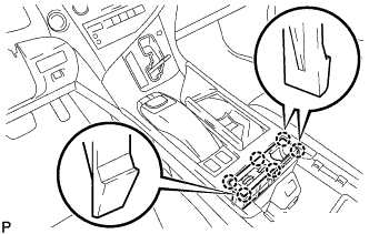
Pull the upper console panel sub-assembly in the direction indicated by the arrow to disengage the 3 claws and 3 clips.
-
Disconnect each connector.
-
Disengage the clamp and remove the upper console panel sub-assembly.
-
- Click here
REMOVE LOWER INSTRUMENT PANEL FINISH PANEL
-
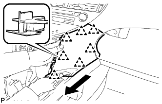
Pull the lower instrument panel finish panel in the direction indicated by the arrow to disengage the 7 clips and remove the lower instrument panel finish panel.
-
- Click here
REMOVE FRONT DOOR SCUFF PLATE RH
Tip:Use the same procedure as for the LH side (Click here).
- Click here
REMOVE COWL SIDE TRIM SUB-ASSEMBLY RH
Tip:Use the same procedure as for the LH side (Click here).
- Click here
REMOVE NO. 2 INSTRUMENT PANEL UNDER COVER SUB-ASSEMBLY
-
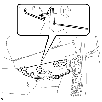
Disengage the 4 claws and 2 guides as shown in the illustration.
-
Disconnect the connector and remove the No. 2 instrument panel under cover sub-assembly.
-
- Click here
REMOVE INSTRUMENT PANEL GARNISH RH (w/o Airbag Cut Off Switch)
Tip:Use the same procedure as for the LH side.
- Click here
REMOVE INSTRUMENT PANEL GARNISH RH (w/ Airbag Cut Off Switch)
-
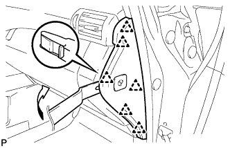
Using moulding remover B, disengage the 6 clips as shown in the illustration.
-
Disconnect the connector and remove the instrument panel garnish RH.
-
- Click here
REMOVE FRONT PASSENGER SIDE KNEE AIRBAG ASSEMBLY
CAUTION:When storing the front passenger side knee airbag assembly, keep the airbag deployment side facing upward.
-
Check that the power switch is off.
-
Check that the cable is disconnected from the negative (-) battery terminal.
CAUTION:Wait at least 90 seconds after disconnecting the cable from the negative (-) battery terminal to disable the SRS system.
-
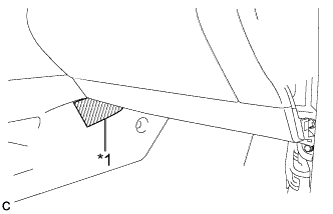
Put protective tape around the front passenger side knee airbag assembly.
Table 2. Text in Illustration *1 Protective Tape -
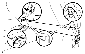
Remove the 3 bolts.
-
Disengage the claw and 2 pins to separate the front passenger side knee airbag assembly.
-
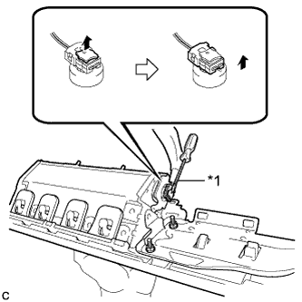
Using a screwdriver with the tip wrapped with protective tape, disconnect the airbag connector to remove the front passenger side knee airbag assembly.
Table 3. Text in Illustration *1 Protective Tape Note:When disconnecting any airbag connector, take care not to damage the airbag wire harness.
-
- Click here
REMOVE GLOVE COMPARTMENT DOOR ASSEMBLY
-
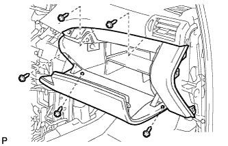
Remove the 5 screws <F>.
-
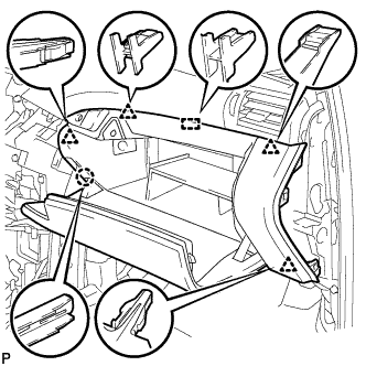
Disengage the claw, 4 clips and guide.
-
Disconnect each connector and remove the glove compartment door assembly.
-
- Click here
REMOVE ECU INTEGRATION BOX RH
-
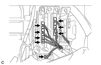
Disconnect each connector.
-
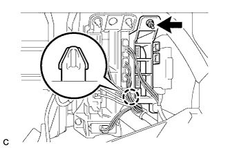
Remove the nut.
-
Disengage the claw and remove the No. 3 connector holder.
-
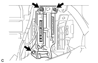
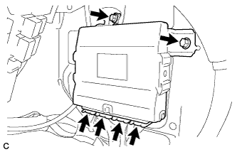
Remove the 2 nuts, bolt and ECU integration box RH.
-
- Click here
REMOVE SKID CONTROL ECU ASSEMBLY
-
Remove the 2 bolts and skid control ECU.
-
Disconnect the 4 connectors from the skid control ECU.
-
- Click here
REMOVE SUSPENSION CONTROL ECU
-
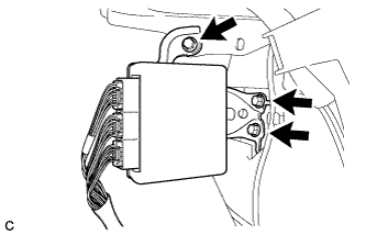
Remove the 3 bolts and suspension control ECU from the body.
Note:
-
Avoid any impact to the suspension control ECU.
-
Do not drop the ECU. If the ECU is dropped, replace it with a new one.
-
-
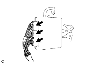
Disconnect the 3 connectors.
-