SHIFT LEVER REMOVAL

-
PRECAUTION (w/ Navigation System for HDD)
Note
After the power switch is turned off, the display and navigation module display (HDD navigation system) records various types of memory and settings. As a result, after turning the power switch off, make sure to wait for the time specified in the following table before disconnecting the cable from the negative (-) battery terminal.
Waiting Time before Disconnecting Cable from Negative (-) Battery Terminal Specification Waiting Time w/o Telematics Transceiver 60 sec. w/ Telematics Transceiver 120 sec. -
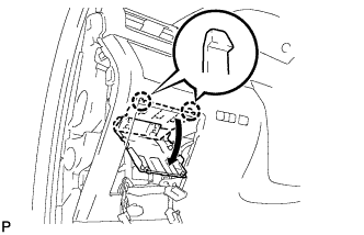
REMOVE REAR DECK FLOOR BOX
-
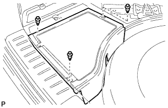
Remove the 3 clips and the rear deck floor box.
-
-
DISCONNECT CABLE FROM NEGATIVE BATTERY TERMINAL
Note
When disconnecting the cable, some systems need to be initialized after the cable is reconnected Click here.
-
REMOVE SHIFT LEVER KNOB SUB-ASSEMBLY
-
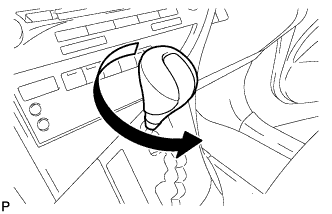
Turn the shift lever knob sub-assembly counterclockwise and remove the shift lever knob sub-assembly.
-
-
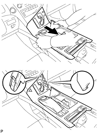
REMOVE UPPER CONSOLE PANEL SUB-ASSEMBLY
-
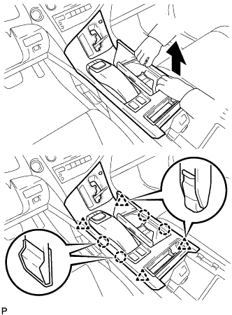
Move the shift lever to N.
-
Pull the upper console panel sub-assembly in the direction indicated by the arrow to disengage the 4 claws and 4 clips.
-
w/o Seat Heater System:
-
Disconnect the connector from the console box hole cover.
-
-
w/ Seat Heater System:
-
Disengage the 6 claws.
-
Disconnect the connector and remove the seat heater switch with console box hole cover.
-
-
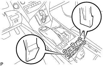
Pull the upper console panel sub-assembly in the direction indicated by the arrow to disengage the 3 claws and 3 clips.
-
Disconnect each connector.
-
Disengage the clamp and remove the upper console panel sub-assembly.
-
-
REMOVE NO. 2 CONSOLE BOX DUCT
-
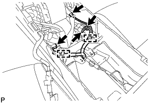
Disconnect each connector and disengage the 2 clamps.
-
Remove the 2 screws and the No. 2 console box duct.
-
-
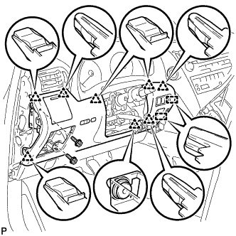
REMOVE CONSOLE REAR END PANEL SUB-ASSEMBLY
-
w/o Rear Seat Entertainment System:
-
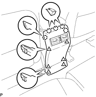
Disengage the 5 claws and 6 clips, and remove the console rear end panel sub-assembly.
-
-
w/ Rear Seat Entertainment System:
-
Disengage the 5 claws and 6 clips.
-
Disconnect each connector and remove the console rear end panel sub-assembly.
-
-
-
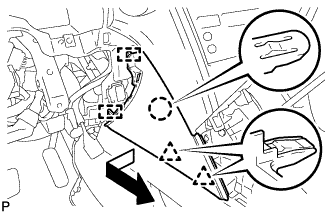
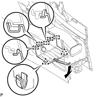
REMOVE REAR CONSOLE BOX ASSEMBLY
-
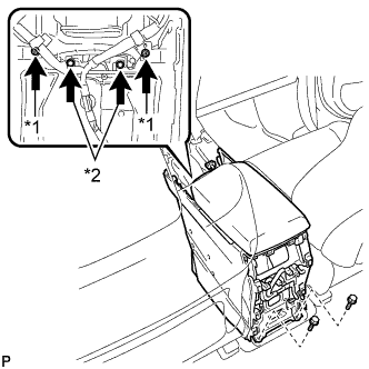
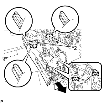
Text in Illustration *1 Screw *2 Bolt Remove the 2 screws and 4 bolts.
-
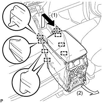
Pull the rear console box assembly in the direction indicated by the arrow (1) to disengage the 8 guides and remove the rear console box assembly as shown in the illustration.
Note
Make sure to remove the rear console box assembly in the direction indicated by the arrow (2). Failure to do so will damage the console box and front seat.
-
-
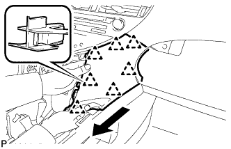
REMOVE INSTRUMENT PANEL GARNISH LH
-
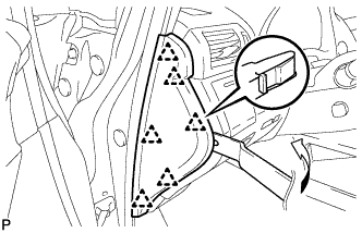
Using moulding remover B, disengage the 6 clips and remove the instrument panel garnish LH as shown in the illustration.
-
-
REMOVE NO. 1 SWITCH HOLE BASE
-
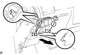
Push the No. 1 switch hole base in the direction indicated by the arrow to disengage the 4 claws and 2 guides.
-
Disconnect each connector and remove the No. 1 switch hole base.
-
-
REMOVE LOWER INSTRUMENT PANEL FINISH PANEL SUB-ASSEMBLY
-
Disengage the 2 claws and open the cover as shown in the illustration.
-
Remove the 2 screws <D>.
-
Disengage the 8 clips and 2 guides.
-
Disconnect each connector and remove the lower instrument panel finish panel sub-assembly.
-
-
REMOVE INSTRUMENT PANEL FINISH PANEL
-
Pull the instrument panel finish panel in the direction indicated by the arrow to disengage the claw, 2 clips and 2 guides, and remove the instrument panel finish panel.
-
-
REMOVE LOWER INSTRUMENT PANEL FINISH PANEL
-
Pull the lower instrument panel finish panel in the direction indicated by the arrow to disengage the 7 clips and remove the lower instrument panel finish panel.
-
-
REMOVE FRONT CONSOLE BOX COVER
-
Using moulding remover A, disengage the 2 clips and 5 guides.
-
Disconnect the connector and remove the front console box cover.
-
-
REMOVE CONSOLE BOX (for LHD)
-
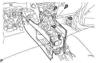
Remove the 5 screws <D>.
-
Text in Illustration *1 Clamp *2 Guide Disengage the 2 clamps.
-
Remove the 3 clips.
-
Disengage the 3 guides and remove the console box as shown in the illustration.
-
-
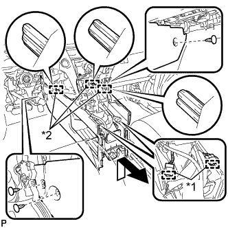
REMOVE CONSOLE BOX (for RHD)
-
Remove the 5 screws <D>.
-
Text in Illustration *1 Clamp *2 Guide Disengage the 2 clamps.
-
Remove the 2 clips.
-
Disengage the 3 guides and remove the console box as shown in the illustration.
-
-
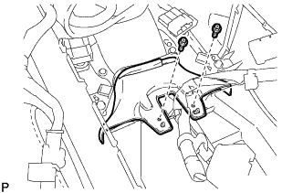
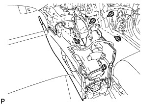
REMOVE SHIFT LEVER ASSEMBLY
-
Move the shift lever to N.
-
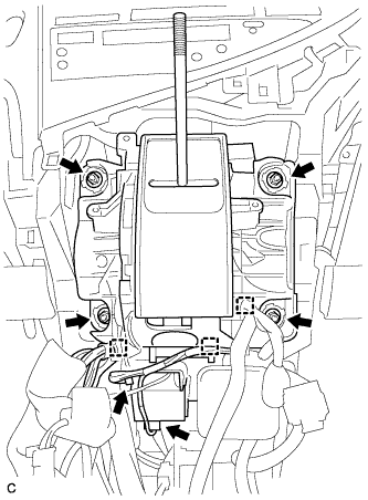
Disconnect the shift lock control ECU connector and transmission control switch wire connector.
-
Disconnect the 3 clamps.
-
Remove the 4 nuts and shift lever assembly.
-
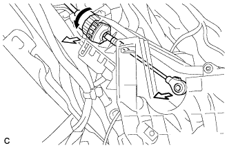
Disconnect the end of the transmission control cable assembly from the shift lever assembly.
-
Turn the lock nut counterclockwise. While holding the lock nut, disconnect the transmission control cable from the shift lever retainer.
-