INPUT SHAFT OIL SEAL REPLACEMENT

-
REMOVE ENGINE ASSEMBLY WITH TRANSAXLE
Tech Tips
Refer to the procedure up to Remove Engine Assembly with Transaxle Click here.
-
REMOVE FRONT FRAME ASSEMBLY
-
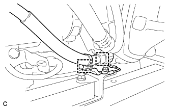
Disconnect the 2 clamps and engine wire from the front frame assembly.
-
Remove the bolt and HV transaxle mass damper.
-
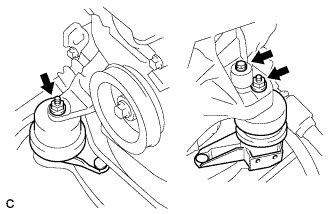
Remove the 2 nuts and separate the engine mounting insulators LH and RH.
-
Remove the bolt and separate the front engine mounting insulator.
-
Remove the 2 bolts and separate the rear engine mounting insulator.
Note
Do not remove the rear engine mounting insulator assembly through bolts. Doing so makes it difficult to install the rear engine mounting insulator assembly.
-
Remove the front frame assembly.
-
-
REMOVE MANIFOLD STAY
-
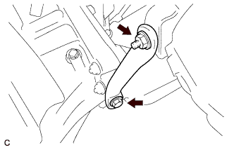
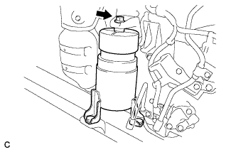
Remove the bolt, nut and manifold stay.
-
-
SEPARATE ENGINE WIRE
-
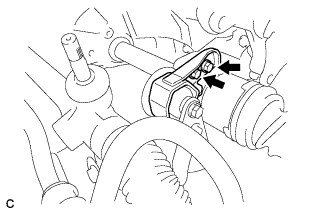
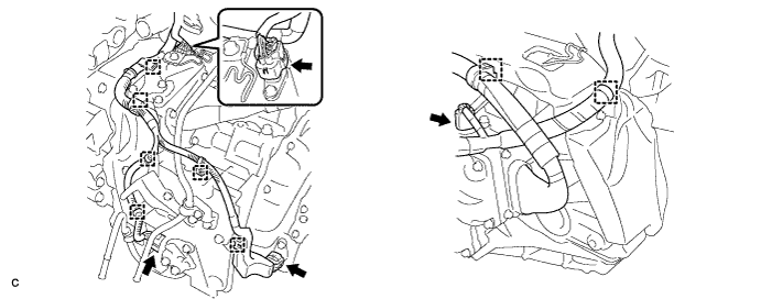
Disconnect the 4 connectors and 8 wire harness clamps.
-
-
REMOVE NO. 3 AUTOMATIC TRANSMISSION CASE COVER
-
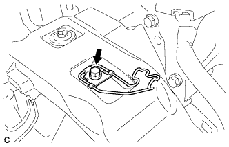
Remove the bolt and No. 3 transmission control cable bracket.
-
Remove the 2 bolts, clip and No. 3 automatic transmission case cover from the transaxle.
-
-
REMOVE FRONT ENGINE MOUNTING BRACKET
-
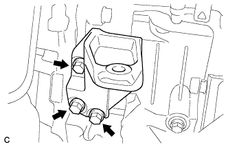
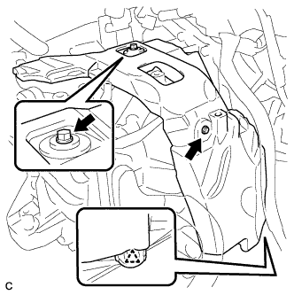
Remove the 3 bolts and front engine mounting bracket.
-
-
REMOVE AUTOMATIC TRANSMISSION CASE COVER
-
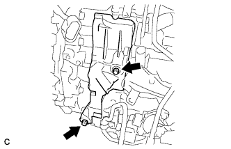
Remove the 2 bolts and automatic transmission case cover.
-
-
REMOVE HYBRID VEHICLE TRANSAXLE ASSEMBLY
-
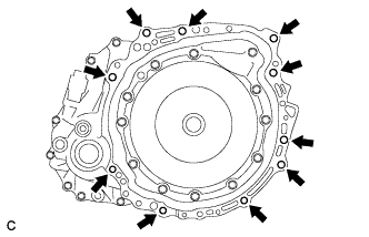
Remove the 10 bolts.
-
Separate and remove the hybrid vehicle transaxle assembly.
Note
Do not pry between the transaxle assembly and engine more than necessary to prevent the knock pins from being damaged.
-
-
REMOVE INPUT SHAFT OIL SEAL
-
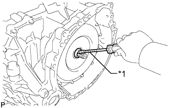
Text in Illustration *1 Vinyl Tape Using a screwdriver with the tip taped, remove the oil seal.
-
-
INSTALL INPUT SHAFT OIL SEAL
-
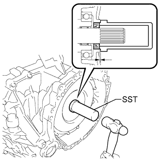
Using SST and a hammer, drive in a new oil seal.
- SST
- 09388-40010
Oil seal driven in depth 1.0 to 1.8 mm (0.0393 to 0.0708 in.)
-
-
INSTALL HYBRID VEHICLE TRANSAXLE ASSEMBLY
-
Make sure that the knock pins are installed on the engine.
-
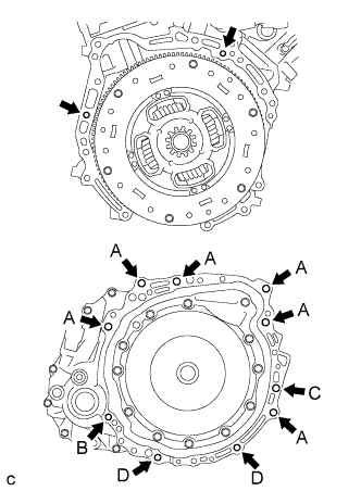
Install the hybrid vehicle transaxle with the 10 bolts shown in the illustration to the engine.
- Torque:
- Bolt A
- 64 N*m { 653 kgf*cm, 47 ft.*lbf }
- Torque:
- Bolt B
- 46 N*m { 469 kgf*cm, 34 ft.*lbf }
- Torque:
- Bolt C
- 64 N*m { 653 kgf*cm, 47 ft.*lbf }
- Torque:
- Bolt D
- 43 N*m { 438 kgf*cm, 32 ft.*lbf }
Note
-
Do not reuse bolt B.
-
Do not forcibly pry on the hybrid vehicle transaxle assembly.
-
Do not apply grease either to the splines or to the input shaft.
Bolt Installation Direction Diameter Bolt Length A From transaxle to engine 12 mm (0.472 in.) 55 mm (2.17 in.) B From engine to transaxle 10 mm (0.393 in.) 41 mm (1.61 in.) C From transaxle to engine 12 mm (0.472 in.) 65 mm (2.55 in.) D From engine to transaxle 10 mm (0.393 in.) 33 mm (1.30 in.)
-
-
INSTALL AUTOMATIC TRANSMISSION CASE COVER
-
Install the automatic transmission case cover with the 2 bolts.
- Torque:
- 7.0 N*m { 71 kgf*cm, 62 in.*lbf }
-
-
INSTALL FRONT ENGINE MOUNTING BRACKET
-
Install the front engine mounting bracket with the 3 bolts.
- Torque:
- 64 N*m { 653 kgf*cm, 47 ft.*lbf }
-
-
INSTALL NO. 3 AUTOMATIC TRANSMISSION CASE COVER
-
Install the No. 3 automatic transmission case cover with the 2 bolts and clip.
- Torque:
- 8.4 N*m { 85 kgf*cm, 74 in.*lbf }
-
Install the No. 3 transmission control cable bracket with the bolt.
- Torque:
- 12 N*m { 122 kgf*cm, 9 ft.*lbf }
-
-
CONNECT ENGINE WIRE
-
Connect the 4 connectors and 8 wire harness clamps to the hybrid vehicle transaxle.
-
-
INSTALL MANIFOLD STAY
-
Install the manifold stay with the bolt and nut.
- Torque:
- Bolt
- 34 N*m { 347 kgf*cm, 25 ft.*lbf }
- Nut
- 35 N*m { 357 kgf*cm, 26 ft.*lbf }
-
-
INSTALL FRONT FRAME ASSEMBLY
-
Install the engine mounting insulators RH and LH with the 2 nuts.
- Torque:
- 95 N*m { 969 kgf*cm, 70 ft.*lbf }
-
Install the HV transaxle mass damper with the bolt.
- Torque:
- 14 N*m { 138 kgf*cm, 10 ft.*lbf }
-
Install the front engine mounting insulator with the bolt.
- Torque:
- 87 N*m { 887 kgf*cm, 64 ft.*lbf }
-
Install the rear engine mounting insulator assembly with the 2 bolts.
- Torque:
- 75 N*m { 765 kgf*cm, 55 ft.*lbf }
-
Connect the engine wire with the 2 clamps.
-
-
INSTALL ENGINE ASSEMBLY WITH TRANSAXLE
Tech Tips
Refer to the procedure from Install Engine Assembly with Transaxle Click here.