- Click here
INSTALL NO. 2 RADIATOR ASSEMBLY
-
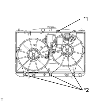
Install the fan assembly with motor to the radiator with the 3 guides at the bottom and attach the claw.
Table 1. Text in Illustration *1 Claw *2 Guide -
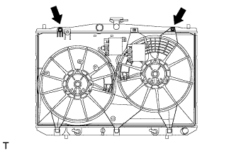
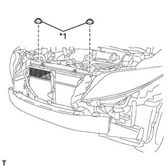
Install the 2 bolts.
8.0 N*m 82 kgf*cm 71 in.*lbf -
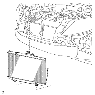
Install the 2 lower radiator supports to the radiator, and install the radiator assembly and fan assembly with motor.
Note:Do not apply any excessive force to the cooler condenser assembly or pipe when installing the radiator assembly.
-
Install the 4 bolts.
6.0 N*m 61 kgf*cm 53 in.*lbf -
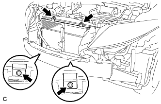
Install the 2 radiator support cushions.
Table 2. Text in Illustration *1 Radiator Support Cushion -
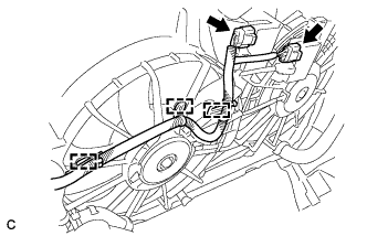
Connect the 3 wire harness clamps and 2 connectors.
-
- Click here
INSTALL UPPER RADIATOR SUPPORT
-
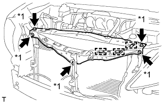
Install the upper radiator support with the 5 bolts and connect the 3 clamps of the hood lock control cable to the upper radiator support.
Table 3. Text in Illustration *1 Bolt 5.5 N*m 56 kgf*cm 49 in.*lbf
-
- Click here
INSTALL HOOD LOCK ASSEMBLY
Tip:
-
Install Hood Lock Assembly (for LHD) (Click here).
-
Install Hood Lock Assembly (for RHD) (Click here).
-
- Click here
INSTALL HOOD LOCK CONTROL CABLE COVER
Tip:
-
Install Hood Lock Control Cable Cover (for LHD) (Click here).
-
Install Hood Lock Control Cable Cover (for RHD) (Click here).
-
- Click here
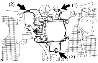
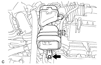
INSTALL SMOG VENTILATION SENSOR (w/ Smog Ventilation Sensor)
-
Engage the guide.
-
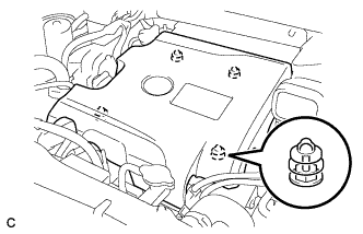
Install the smog ventilation sensor with the bolt.
9.8 N*m 100 kgf*cm 87 in.*lbf -
Connect the connector.
-
- Click here
INSTALL HIGH PITCHED HORN ASSEMBLY (for RHD)
-
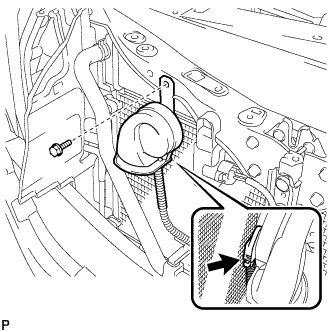
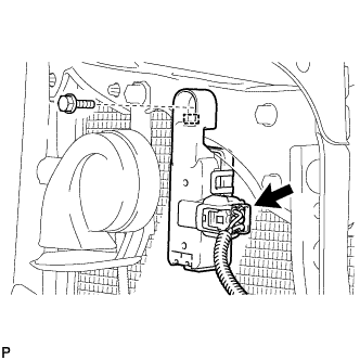
Install the high pitched horn assembly with the bolt.
19 N*m 194 kgf*cm 14 ft.*lbf -
Connect the connector.
-
- Click here
INSTALL LOW PITCHED HORN ASSEMBLY (for LHD)
-
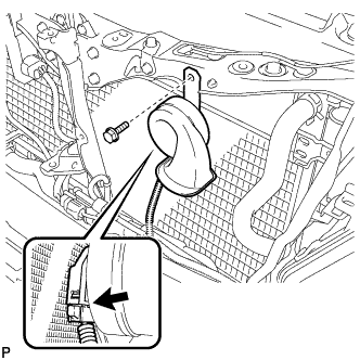
Install the low pitched horn assembly with the bolt.
19 N*m 194 kgf*cm 14 ft.*lbf -
Connect the connector.
-
- Click here
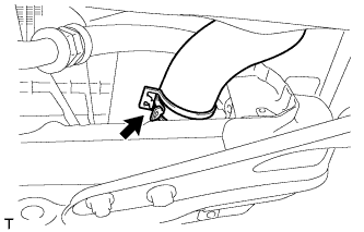
INSTALL MILLIMETER WAVE RADAR SENSOR ASSEMBLY (w/ Dynamic Radar Cruise Control System)
-
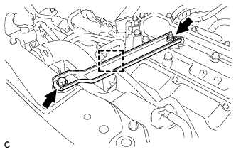
Tighten the 3 bolts on the millimeter wave radar sensor assembly.
5.5 N*m 56 kgf*cm 49 in.*lbf Tip:Tighten the bolts in the order indicated in the illustration.
-
Connect the connector.
-
- Click here
CONNECT NO. 2 RADIATOR HOSE
-
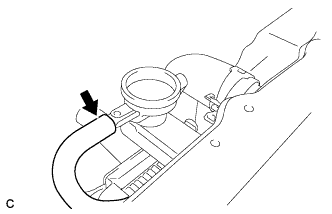
Connect the No. 2 radiator hose to the radiator.
-
- Click here
CONNECT NO. 1 RADIATOR HOSE
-
Connect the No. 1 radiator hose to the radiator.
-
- Click here
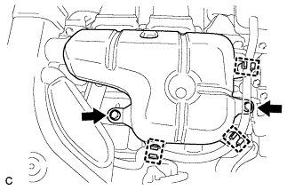
INSTALL RADIATOR RESERVE TANK ASSEMBLY
-
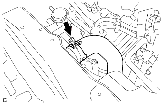
Connect the radiator reserve tank hose to the radiator.
-
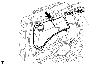
Install the radiator reserve tank with the bolt and connect the 2 clamps to the radiator.
5.3 N*m 54 kgf*cm 47 in.*lbf
-
- Click here
INSTALL FRONT BUMPER ASSEMBLY (for Sport Package)
- Click here
INSTALL FRONT BUMPER ASSEMBLY (for Standard)
- Click here
INSTALL NO. 3 INVERTER BRACKET
-
Install the No. 3 inverter bracket with the 2 bolts.
10 N*m 102 kgf*cm 7 ft.*lbf -
Install the hose clamp to the No. 3 inverter bracket.
-
- Click here
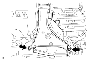
INSTALL NO. 1 AIR CLEANER INLET
-
Install the inlet No. 1 air cleaner with the bolt.
8.0 N*m 82 kgf*cm 71 in.*lbf -
Connect the No. 1 fuel vapor feed hose to the inlet No. 1 air cleaner.
-
- Click here
INSTALL NO. 2 AIR CLEANER INLET
-
Install the inlet No. 2 air cleaner with the 2 bolts.
8.0 N*m 82 kgf*cm 71 in.*lbf
-
- Click here
INSTALL INTAKE AIR RESONATOR SUB-ASSEMBLY
-
Install the intake air resonator sub-assembly to the inverter with converter assembly with the 2 bolts.
8.0 N*m 82 kgf*cm 71 in.*lbf -
Install the water hose with the 3 clamps to the intake air resonator sub-assembly.
-
- Click here
ADD COOLANT (for Engine)
-
Tighten the radiator drain cock plug by hand.
-
Tighten the cylinder block drain cock plug. (for Bank 1)
13 N*m 130 kgf*cm 9 ft.*lbf -
Tighten the cylinder block drain cock plug. (for Bank 2, w/ Cylinder Block Drain Cock Plug)
13 N*m 130 kgf*cm 9 ft.*lbf -
Loosen the air drain cock plug on the water inlet housing.
-
Add engine coolant to the radiator inlet opening until engine coolant overflows from the air drain cock hole. Then tighten the air drain cock plug to the water inlet housing.
13 N*m 130 kgf*cm 9 ft.*lbf -
Slowly fill the radiator assembly with engine coolant.
Table 4. Standard Capacity Item Capacity Engine coolant 11.7 liters (12.4 US qts, 10.2 lmp. qts) Note:Never use water as a substitute for engine coolant.
Tip:TOYOTA vehicles are filled with TOYOTA SLLC at the factory. In order to avoid damage to the engine cooling system and other technical problems, only use TOYOTA SLLC or similar high quality ethylene glycol based non-silicate, non-amine, non-nitrite, non-borate coolant with long-life hybrid organic acid technology (coolant with long-life hybrid organic acid technology is a combination of low phosphates and organic acids).
-
Remove the reserve tank cap.
-
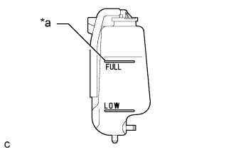
Slowly pour engine coolant into the radiator reserve tank assembly until it reaches the full line.
Table 5. Text in Illustration *a Full Line -
Squeeze the No. 1 radiator hose and No. 2 radiator hose several times by hand, and then check the level of the engine coolant.
If the engine coolant level is low, add engine coolant.
-
Install the radiator cap sub-assembly and reserve tank cap.
-
Bleed air from the cooling system.
-
Put the engine in inspection mode (Click here).
-
Warm up the engine until the thermostat opens. While the thermostat is open, circulate the engine coolant for several minutes.
Tip:The thermostat open timing can be confirmed by squeezing the No. 2 radiator hose by hand, and sensing vibrations when the engine coolant starts to flow inside the No. 2 radiator hose.
-
Maintain the engine speed at 2500 rpm.
-
Squeeze the No. 1 radiator hose and No. 2 radiator hose several times by hand to bleed air.
CAUTION:When squeezing the No. 1 radiator hose and No. 2 radiator hose:
-
Wear protective gloves.
-
Be careful as the No. 1 radiator hose and No. 2 radiator hose are hot.
-
Keep your hands away from the fan and No. 2 fan.
Note:
-
If the coolant temperature gauge indicates an excessive temperature, turn off the engine and let it cool.
-
Make sure that the radiator reserve tank assembly still has some engine coolant in it.
-
If the radiator reserve tank assembly does not have enough engine coolant, the engine may overheat or be seriously damaged.
-
If the radiator reserve tank assembly does not have enough engine coolant, perform the following: 1) stop the engine, 2) wait until the engine coolant has cooled down, and 3) add engine coolant until the radiator reserve tank assembly is filled to the full line.
-
-
-
Stop the engine, and wait until the engine coolant cools down.
-
Add engine coolant to the full line on the radiator reserve tank assembly.
-
- Click here
INSPECT FOR COOLANT LEAK (for Engine)
CAUTION:Do not remove the radiator cap while the engine and radiator are still hot. Pressurized hot engine coolant and steam may be released and cause serious burns.
Note:Before performing each inspection, turn the A/C switch off.
-
Remove the radiator cap.
-
Fill the radiator with coolant and attach a radiator cap tester.
-
Put the engine in inspection mode (Click here).
-
Warm up the engine.
-
Using the radiator cap tester, increase the pressure inside the radiator to 118 kPa (1.2 kgf/cm2, 17 psi), and check that the pressure does not drop.
If the pressure drops, check the hoses, radiator, exhaust center pipe assembly and the heater hose around the water temperature switch and engine water pump for leaks. If no external leaks are found, check the heater core, cylinder block and cylinder head.
-
Remove the radiator cap tester.
-
Install the radiator cap.
-
- Click here
INSPECT HYBRID TRANSAXLE FLUID
-
Set the vehicle to FWD inspection mode (Click here).
-
After waiting for 1 minute or more, stop the engine.
-
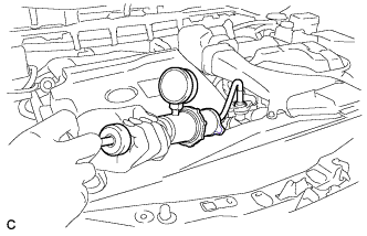
Using a hexagon socket wrench 10 mm, remove the filler plug and gasket.
Table 6. Text in Illustration *1 Filler Plug -
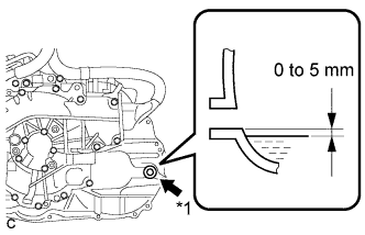
Add transaxle fluid until the transaxle fluid level is between 0 and 5 mm (0 and 0.197 in.) from the bottom lip of the filler plug opening.
Note:
-
Keep the transaxle fluid temperature at 5°C (41°F) or higher.
-
Stop the vehicle on a flat road.
-
Recheck the transaxle fluid level after driving following transaxle fluid replacement.
-
Insufficient or excessive amounts of transaxle fluid may be the cause of some trouble.
-
Be sure to add fluid slowly. If fluid is added quickly, the fluid may hit internal parts and bounce back, resulting in fluid coming out of the filler plug opening.
-
Be sure to directly check that the transaxle fluid level is within the specified range.
-
-
After adding fluid, leave it for 30 seconds so that the fluid surface can become still again, and then check that the fluid level is between 0 to 5 mm (0 to 0.197 in.) from the bottom lip of the filler plug opening. (If the fluid is insufficient, return to the Add Hybrid Transaxle Fluid procedure.)
-
Check for leaks if the quantity of transaxle fluid is low.
-
Using a hexagon socket wrench 10 mm, install the filler plug and a new gasket.
39 N*m 398 kgf*cm 29 ft.*lbf
-
- Click here
INSPECT FOR OIL LEAK
-
Put the engine in inspection mode (Click here).
-
Start the engine.
-
Check for engine oil leaks from the connected parts of the oil filter cap and oil filter drain plug.
-
- Click here
INSTALL NO. 1 ENGINE UNDER COVER
- Click here
INSTALL V-BANK COVER SUB-ASSEMBLY
-
Engage the 4 retainers and install the V-bank cover sub-assembly.
-
- Click here
CONNECT CABLE TO NEGATIVE AUXILIARY BATTERY TERMINAL
Note:When disconnecting the cable, some systems need to be initialized after the cable is reconnected (Click here).
- Click here
ADJUST MILLIMETER WAVE RADAR SENSOR (w/ Dynamic Radar Cruise Control System)