EXHAUST MANIFOLD INSTALLATION

-
INSTALL NO. 2 AIR FUEL RATIO SENSOR (for Bank 2 Sensor 1)
-
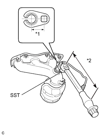
Text in Illustration *1 Fulcrum Length
30 mm
*2 Fulcrum Length
300 mm
Using SST, install the air fuel ratio sensor to the exhaust manifold LH.
- SST
- 09224-00010
- Torque:
- without SST
- 44 N*m { 449 kgf*cm, 32 ft.*lbf }
- with SST
- 40 N*m { 408 kgf*cm, 30 ft.*lbf }
Note
-
The "with SST" torque value is effective when using SST with a fulcrum length of 30 mm (1.18 in.).
-
The "with SST" torque value is effective when using a torque wrench with a fulcrum length of 300 mm (11.81 in.) Click here.
-
The "with SST" torque value is effective when SST is parallel to the torque wrench.
-
-
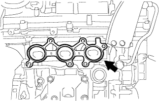
INSTALL EXHAUST MANIFOLD TO HEAD GASKET LH
-
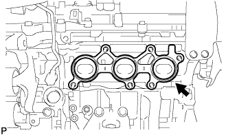
Install a new exhaust manifold to head gasket LH.
-
-
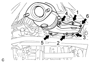
INSTALL EXHAUST MANIFOLD SUB-ASSEMBLY LH
-
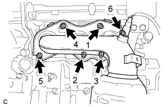
Using a 12 mm deep socket wrench, install the exhaust manifold sub-assembly LH and 6 nuts in the order shown in the illustration.
- Torque:
- 21 N*m { 214 kgf*cm, 15 ft.*lbf }
-
-
INSTALL NO. 2 EXHAUST MANIFOLD HEAT INSULATOR
-
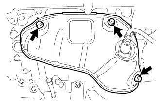
Install the No. 2 exhaust manifold heat insulator with the 3 bolts.
- Torque:
- 8.5 N*m { 87 kgf*cm, 75 in.*lbf }
-
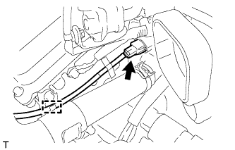
Connect the sensor wire to the radiator pipe clamp.
-
Connect the air fuel ratio sensor connector (for Bank 2 Sensor 1).
-
-
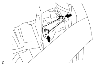
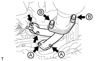
INSTALL NO. 2 MANIFOLD STAY
-
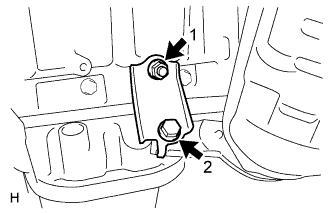
Install the No. 2 manifold stay by tightening the bolt and nut in the order shown in the illustration.
- Torque:
- 34 N*m { 347 kgf*cm, 25 ft.*lbf }
-
-
INSTALL NO. 2 ENGINE OIL LEVEL DIPSTICK GUIDE
-
Install a new O-ring to the No. 2 engine oil level dipstick guide.
-
Apply a light coat of engine oil to the O-ring.
-
Push in the No. 2 engine oil level dipstick guide end into the No. 1 engine oil level dipstick guide.
-
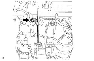
Install the No. 2 engine oil level dipstick guide with the bolt.
- Torque:
- 21 N*m { 214 kgf*cm, 15 ft.*lbf }
-
Install the engine oil level dipstick.
-
-
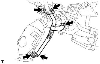
INSTALL FRONT EXHAUST PIPE ASSEMBLY
-
Install a new gasket to the front exhaust pipe assembly.
-
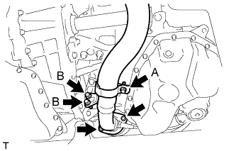
Install the front exhaust pipe assembly with the 2 nuts and 2 bolts (B).
- Torque:
- Bolt B
- 21 N*m { 214 kgf*cm, 15 ft.*lbf }
- Nut
- 55 N*m { 561 kgf*cm, 40 ft.*lbf }
-
Tighten the bolt (A).
- Torque:
- Bolt A
- 21 N*m { 214 kgf*cm, 15 ft.*lbf }
-
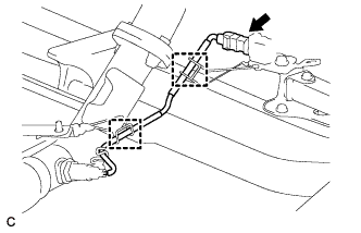
Connect the 2 clamps and No. 2 oxygen sensor connector (for Bank 2 Sensor 2).
-
-
INSTALL AIR FUEL RATIO SENSOR (for Bank 1 Sensor 1)
Tech Tips
Use the same procedure for bank 1 and bank 2.
- SST
- 09224-00010
- Torque:
- without SST
- 44 N*m { 449 kgf*cm, 32 ft.*lbf }
- with SST
- 40 N*m { 408 kgf*cm, 30 ft.*lbf }
Note
-
The "with SST" torque value is effective when using SST with a fulcrum length of 30 mm (1.18 in.).
-
The "with SST" torque value is effective when using a torque wrench with a fulcrum length of 300 mm (11.81 in.) Click here.
-
The "with SST" torque value is effective when SST is parallel to the torque wrench.
-
INSTALL EXHAUST MANIFOLD TO HEAD GASKET
-
Install a new exhaust manifold to head gasket.
-
-
INSTALL EXHAUST MANIFOLD SUB-ASSEMBLY RH
-
Using a 12 mm deep socket wrench, install the exhaust manifold sub-assembly RH by tightening the 6 nuts in the order shown in the illustration.
- Torque:
- 21 N*m { 214 kgf*cm, 15 ft.*lbf }
-
Connect the 2 clamps and air fuel ratio sensor connector (for Bank 1 Sensor 1).
-
-
INSTALL NO. 1 EGR PIPE (w/ EGR System)
-
Install 2 new gaskets and No. 1 EGR pipe with the bolt and 4 nuts.
- Torque:
- 21 N*m { 214 kgf*cm, 15 ft.*lbf }
-
-
INSTALL EGR HOLE COVER PLATE (w/o EGR System)
-
Install a new gasket and EGR hole cover plate with the 2 nuts.
- Torque:
- 21 N*m { 214 kgf*cm, 15 ft.*lbf }
-
-
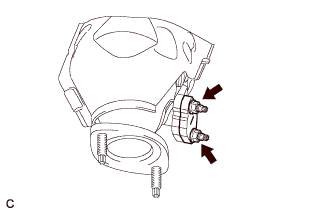
INSTALL MANIFOLD STAY
-
Install the manifold stay with the bolt and nut.
- Torque:
- Bolt
- 34 N*m { 347 kgf*cm, 25 ft.*lbf }
- Nut
- 35 N*m { 357 kgf*cm, 26 ft.*lbf }
-
-
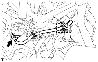
INSTALL FRONT NO. 3 EXHAUST PIPE SUB-ASSEMBLY
-
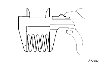
Using a vernier caliper, measure the free length of the compression springs.
Minimum length 41.5 mm (1.64 in.) If the free length is less than the minimum, replace the compression spring.
-
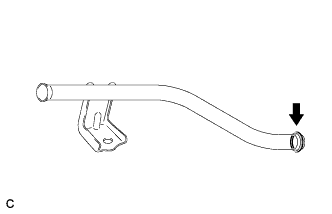
Fully insert a new gasket to the front No. 3 exhaust pipe sub-assembly.
-
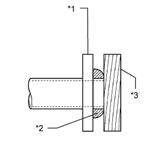
Text in Illustration *1 Front No. 3 Exhaust Pipe Sub-assembly *2 Gasket *3 Wooden Block Using a plastic hammer and wooden block, tap in the new gasket until its surface is flush with the front No. 3 exhaust pipe sub-assembly.
Note
-
Be sure to install the gasket in the correct direction.
-
Do not reuse the gasket.
-
Do not damage the gasket.
-
Do not push in the gasket by using the exhaust pipe when connecting it.
-
-
Install 2 new gaskets to the front No. 3 exhaust pipe sub-assembly.
-
Install the front No. 3 exhaust pipe sub-assembly with the 4 bolts, 2 compression springs and 2 nuts.
- Torque:
- Bolt A
- 55 N*m { 561 kgf*cm, 40 ft.*lbf }
- Bolt B
- 43 N*m { 440 kgf*cm, 32 ft.*lbf }
- Nut
- 55 N*m { 561 kgf*cm, 40 ft.*lbf }
-
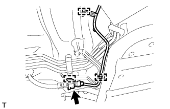
Connect the 3 clamps and oxygen sensor connector (for Bank 1 Sensor 2).
-
-
INSTALL FRONT FLOOR COVER LH
-
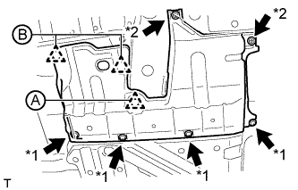
Text in Illustration *1 Bolt *2 Screw Connect the 2 clips (B).
-
Install the front floor cover LH with the 2 screws and 4 bolts.
-
Install the clip (A).
-
-
INSTALL NO. 2 RADIATOR ASSEMBLY
-
Install the No. 2 radiator assembly Click here.
-
-
INSTALL OUTER COWL TOP PANEL SUB-ASSEMBLY
-
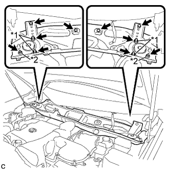
Install the outer cowl top panel sub-assembly with the 4 bolts, 4 nuts*1 and 2 nuts*2.
- Torque:
- Nut*1
- 85 N*m { 867 kgf*cm, 63 ft.*lbf }
- Nut*2
- 5.5 N*m { 56 kgf*cm, 49 in.*lbf }
- Bolt
- 5.5 N*m { 56 kgf*cm, 49 in.*lbf }
-
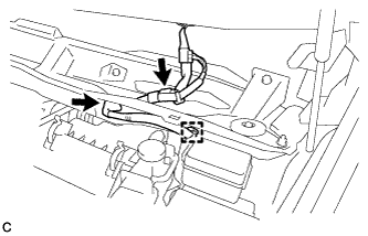
Engage the grommet and clamp.
-
Connect the connector (w/ Windshield Deicer).
-
-
INSTALL FRONT SHOCK ABSORBER CAP LH (w/ Air Suspension)
-
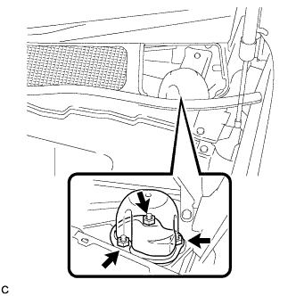
Install the front shock absorber cap with the 3 nuts.
- Torque:
- 14 N*m { 143 kgf*cm, 10 ft.*lbf }
-
-
INSTALL FRONT SHOCK ABSORBER CAP RH (w/ Air Suspension)
Tech Tips
Use the same procedure for the LH side and RH side.
-
INSTALL WINDSHIELD WIPER MOTOR AND LINK ASSEMBLY
-
Install the windshield wiper motor and link assembly Click here.
-
-
INSPECT FOR EXHAUST GAS LEAK