- Click here
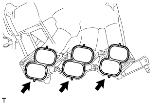
INSTALL INTAKE MANIFOLD
-
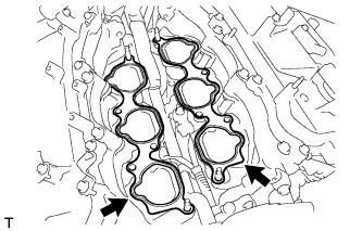
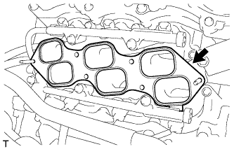
Set 2 new intake manifold gaskets on each cylinder head.
Note:
-
Align the port holes of the gaskets and cylinder head.
-
Make sure that the gaskets are installed in the correct direction.
-
-
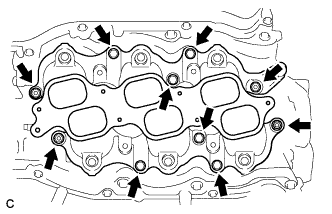
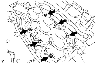
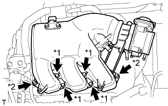
Set the intake manifold on the cylinder head.
-
Install and tighten the 6 bolts and 4 nuts uniformly in several steps.
21 N*m 214 kgf*cm 15 ft.*lbf
-
- Click here
INSTALL FUEL INJECTOR ASSEMBLY
-
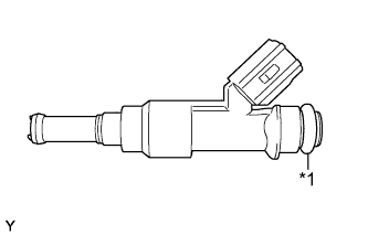
Apply a light coat of spindle oil or gasoline to new O-rings, and install them to each injector.
Table 1. Text in Illustration *1 New O-ring -
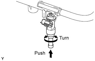
Apply a light coat of spindle oil or gasoline where the fuel delivery pipe contacts each O-ring.
-
Push and twist each fuel injector to install them into the fuel delivery pipe.
-
Position each fuel injector connector outward.
Note:
-
Be careful not to twist the O-rings.
-
After installing a fuel injector, check that it turns smoothly. If not, reinstall it with a new O-ring.
-
-
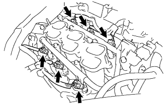
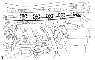
Install 6 new injector vibration insulators to the intake manifold.
-
Place the fuel delivery pipe with the 6 fuel injectors in position on the intake manifold.
Note:Be careful not to drop the fuel injectors when installing the fuel delivery pipe.
-
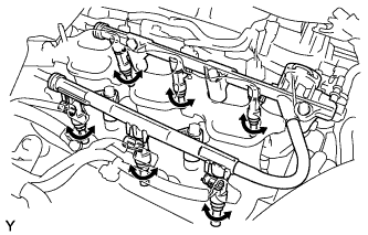
Temporarily install the 5 bolts which are used to hold the fuel delivery pipe to the intake manifold.
Note:After installing the fuel injectors, check that they turn smoothly. If not, reinstall the injectors with new O-rings.
-
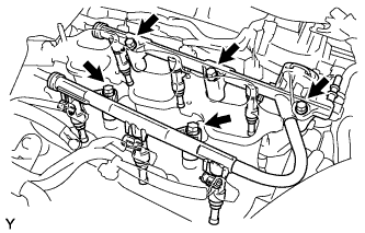
Tighten the 5 bolts which are used to hold the fuel delivery pipe to the intake manifold.
21 N*m 214 kgf*cm 15 ft.*lbf -
Connect the 6 fuel injector connectors.
-
- Click here
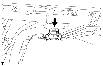
CONNECT FUEL TUBE SUB-ASSEMBLY
-
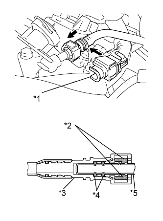
Push in the tube connector onto the pipe until the tube connector makes a "click" sound.
Table 2. Text in Illustration *1 No. 2 Fuel Pipe Clamp *2 Retainer *3 Fuel Tube Connector *4 O-ring *5 Pipe Note:
-
Before connecting the tube, make sure that it is not damaged. Make sure that there is no dirt present on the connecting surfaces.
-
After connecting, check that the fuel tube connector and the pipe are securely connected by pulling on them.
-
-
Install the No. 2 fuel pipe clamp.
-
- Click here
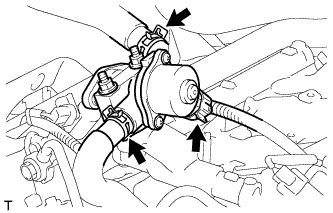
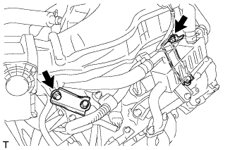
INSTALL NO. 2 ENGINE MOUNTING STAY RH
-
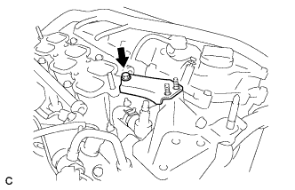
Install the No. 2 engine mounting stay RH with the bolt.
21 N*m 214 kgf*cm 15 ft.*lbf
-
- Click here
INSTALL NO. 2 ENGINE MOUNTING STAY RH
-
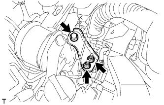
Install the No. 2 engine mounting stay RH with the bolt and 2 nuts.
Bolt 38 N*m 387 kgf*cm 28 ft.*lbf Nut 23 N*m 235 kgf*cm 17 ft.*lbf
-
- Click here
INSTALL EGR DELIVERY CHAMBER
-
Set a new No. 2 intake manifold gasket.
-
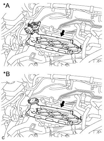
Install the EGR delivery chamber.
Table 3. Text in Illustration *A w/ EGR System *B w/o EGR System -
Connect the 2 water hoses and connector (w/ EGR System).
-
- Click here
INSTALL NO. 2 EGR PIPE (w/ EGR System)
-
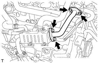
Install 2 new gaskets and the No. 2 EGR pipe with the 2 nuts and 2 bolts.
21 N*m 214 kgf*cm 15 ft.*lbf
-
- Click here
INSTALL INTAKE AIR SURGE TANK ASSEMBLY
NOTICE DO NOT apply oil to the bolts listed below: Tightening Part Surge Tank and Intake Manifold No. 1 Surge Tank Stay and Surge Tank Throttle Body Bracket and Surge Tank
-
Install 3 new air surge tank to intake manifold gaskets to the intake air surge tank.
-
Using a 5 mm hexagon socket wrench, install the intake air surge tank assembly with the 4 bolts and 2 nuts.
Table 4. Text in Illustration *1 Bolt *2 Nut Bolt 18 N*m 184 kgf*cm 13 ft.*lbf Nut 16 N*m 163 kgf*cm 12 ft.*lbf -
Install the throttle body bracket and No. 1 surge tank stay with the 2 bolts.
21 N*m 214 kgf*cm 15 ft.*lbf -
Connect the connector to the manifold absolute pressure sensor.
-
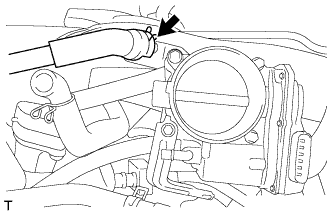
Connect the ventilation hose.
-
Install the 5 clamps and connect the main wire to the body.
-
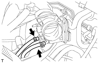
Connect the 2 water by-pass hoses to the throttle body assembly.
-
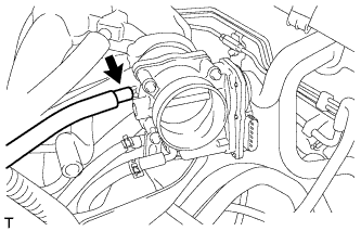
Connect the fuel vapor feed hose.
-
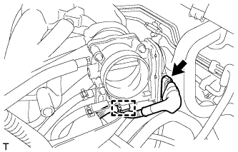
Connect the throttle body assembly connector and wire harness clamp to the throttle body assembly.
-
- Click here
INSTALL AIR CLEANER ASSEMBLY WITH HOSE
-
Install the air cleaner assembly with hose (Click here).
-
- Click here
INSPECT FOR FUEL LEAK
-
Check fuel pump operation.
-
Connect the intelligent tester to the DLC3.
-
Turn the power switch on (IG).
Note:Do not start the engine.
-
Turn the intelligent tester on.
-
Enter the following menus: Powertrain / Engine / Active Test / Control the Fuel Pump / Speed.
-
Check for pressure in the fuel inlet tube from the fuel line. Check that sounds of fuel flowing from the fuel tank can be heard. If no sounds can be heard, check the integration relay, fuel pump, ECM and wiring connectors.
-
-
Inspect for fuel leaks.
-
Check that there are no fuel leaks from the fuel system after doing any maintenance or repairs. If there is a fuel leak, repair or replace parts as necessary.
-
-
Turn the power switch off.
-
Disconnect the intelligent tester from the DLC3.
-