INTAKE MANIFOLD REMOVAL

-
REMOVE AIR CLEANER ASSEMBLY WITH HOSE
-
Remove the air cleaner assembly with hose Click here.
-
-
DISCHARGE FUEL SYSTEM PRESSURE
Tech Tips
-
REMOVE INTAKE AIR SURGE TANK ASSEMBLY
-
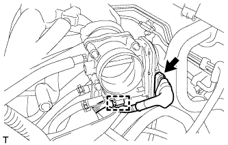
Disconnect the throttle body assembly connector and wire harness clamp.
-
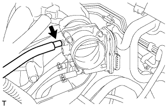
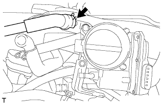
Disconnect the fuel vapor feed hose.
-
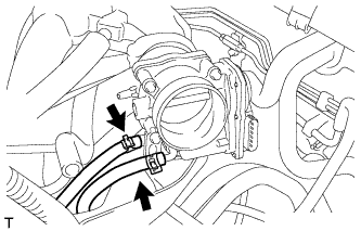
Disconnect the 2 water by-pass hoses.
-
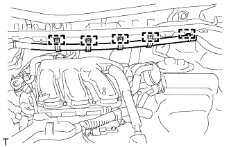
Disconnect the 5 clamps and separate the main wire.
-
Disconnect the ventilation hose.
-
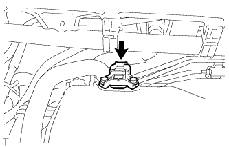
Disconnect the connector from the manifold absolute pressure sensor.
-
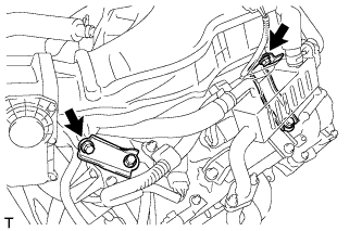
Remove the bolt and separate the No. 1 surge tank stay from the intake air surge tank assembly.
-
Remove the bolt and separate the throttle body bracket from the intake air surge tank assembly.
-
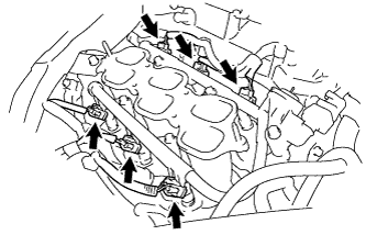
Remove the 2 nuts from the intake air surge tank assembly.
-
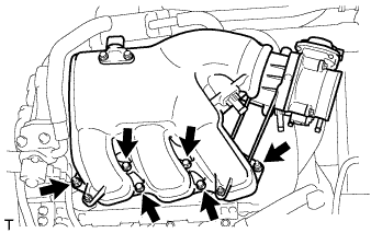
Using a 5 mm socket hexagon wrench, remove the 4 bolts.
-
Remove the intake air surge tank assembly and 3 air surge tank to intake manifold gaskets.
-
-
REMOVE NO. 2 EGR PIPE (w/ EGR System)
-
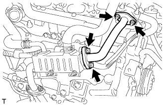
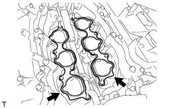
Remove the 2 nuts, 2 bolts, No. 2 EGR pipe and 2 gaskets.
-
-
REMOVE EGR DELIVERY CHAMBER
-
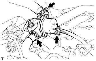
Disconnect the 2 water hoses and connector (w/ EGR System).
-
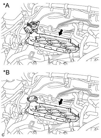
Text in Illustration *A w/ EGR System *B w/o EGR System Remove the EGR delivery chamber.
-
Remove the No. 2 intake manifold gasket.
-
-
REMOVE NO. 2 ENGINE MOUNTING STAY RH
-
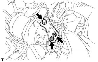
Remove the bolt, 2 nuts and No. 2 engine mounting stay RH.
-
-
REMOVE NO. 2 ENGINE MOUNTING STAY RH
-
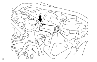
Remove the bolt and No. 2 engine mounting stay RH.
-
-
DISCONNECT FUEL TUBE SUB-ASSEMBLY
-
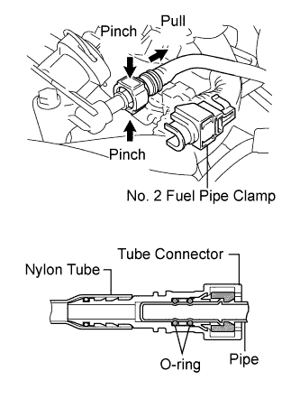
Remove the No. 2 fuel pipe clamp.
-
Pinch the tube connector and pull out the fuel pipe.
Note
-
Check that there is no dirt or other foreign objects around the connector when disconnecting it. Clean the connector as necessary.
-
It is necessary to prevent dirt or foreign objects from entering the quick connector. If dirt or foreign objects get in the connector, the O-rings may not seal properly.
-
Only disconnect the quick connector by hand.
-
Do not bend, kink or twist the nylon tubes.
-
Protect the connector by covering it with a plastic bag.
-
If the pipe and the connector are stuck, carefully try wiggling or pushing and pulling on the connector to release it. Pull the connector off carefully.
-
-
-
REMOVE FUEL INJECTOR ASSEMBLY
-
Disconnect the 6 fuel injector connectors.
-
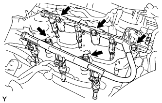
Remove the 5 bolts and fuel delivery pipe sub-assembly together with the 6 fuel injectors.
Note
Be careful not to drop the fuel injectors when removing the fuel delivery pipe.
-
Remove the 6 injector vibration insulators from the intake manifold.
-
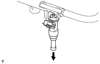
Pull out the fuel injectors from the fuel delivery pipe.
Note
If the injectors are to be reused, reinstall them to the same cylinder they came from.
-
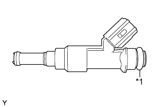
Text in Illustration *1 O-ring Remove the 6 O-rings from the injectors.
-
-
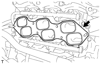
REMOVE INTAKE MANIFOLD
-
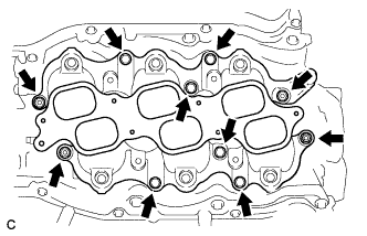
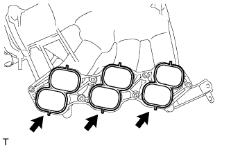
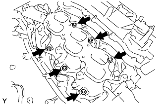
Remove the 6 bolts, 4 nuts and intake manifold.
-
Remove the 2 intake manifold gaskets.
-