ENGINE UNIT REMOVAL

-
INSTALL ENGINE ON ENGINE STAND
-
Install the engine onto an engine stand with the bolts.
-
-
REMOVE ENGINE HANGERS
-
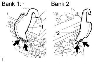
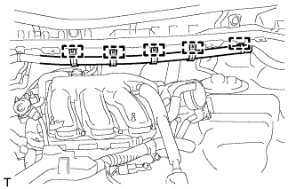
Text in Illustration *1 No. 1 Engine Hanger *2 No. 2 Engine Hanger Remove the 4 bolts and 2 engine hangers.
-
-
REMOVE INTAKE AIR SURGE TANK ASSEMBLY
-
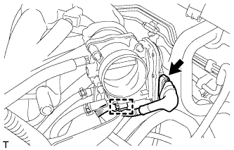
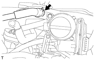
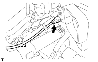
Disconnect the throttle body assembly connector and wire harness clamp.
-
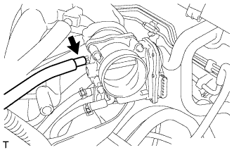
Disconnect the fuel vapor feed hose.
-
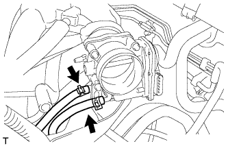
Disconnect the 2 water by-pass hoses.
-
Disconnect the 5 clamps and separate the main wire.
-
Disconnect the ventilation hose.
-
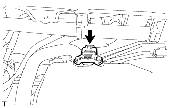
Disconnect the connector from the manifold absolute pressure sensor.
-
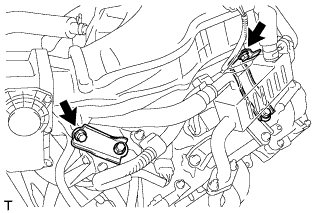
Remove the bolt and separate the No. 1 surge tank stay from the intake air surge tank assembly.
-
Remove the bolt and separate the throttle body bracket from the intake air surge tank assembly.
-
Remove the 2 nuts from the intake air surge tank assembly.
-
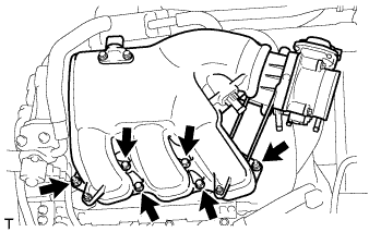
Using a 5 mm socket hexagon wrench, remove the 4 bolts.
-
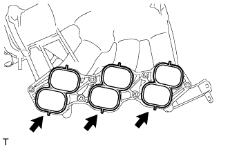
Remove the intake air surge tank assembly and 3 air surge tank to intake manifold gaskets.
-
-
REMOVE THROTTLE BODY BRACKET
-
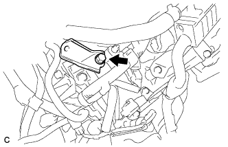
Remove the bolt and throttle body bracket.
-
-
REMOVE NO. 2 EGR PIPE (w/ EGR System)
-
Remove the 2 nuts, 2 bolts, No. 2 EGR pipe and 2 gaskets.
-
-
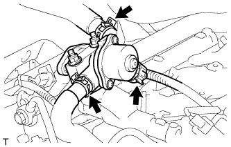
REMOVE EGR COOLER ASSEMBLY (w/ EGR System)
-

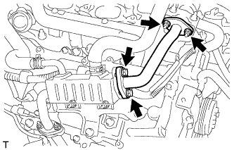
Disconnect the 2 water hoses.
-
Remove the 4 nuts, EGR cooler assembly and gasket.
-
-
REMOVE NO. 1 EGR PIPE (w/ EGR System)
-
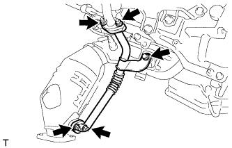
Remove the bolt, 4 nuts, No. 1 EGR pipe and 2 gaskets.
-
-
REMOVE NO. 1 EGR COOLER BRACKET (w/ EGR System)
-
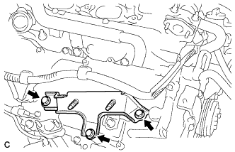
Remove the 3 bolts and No. 1 EGR cooler bracket.
-
-
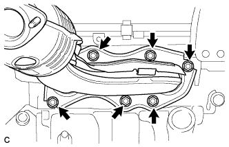
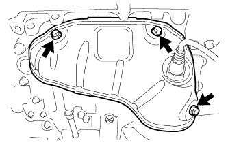
REMOVE EGR DELIVERY CHAMBER
-
Disconnect the 2 water hoses and connector (w/ EGR System).
-
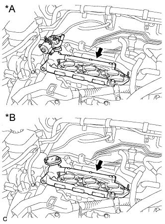
Text in Illustration *A w/ EGR System *B w/o EGR System Remove the EGR delivery chamber.
-
Remove the No. 2 intake manifold gasket.
-
-
REMOVE NO. 1 SURGE TANK STAY
-
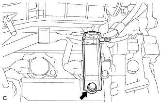
Remove the bolt and No. 1 surge tank stay.
-
-
REMOVE IGNITION COIL ASSEMBLY
-
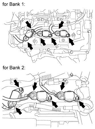
Disconnect the 6 ignition coil connectors.
-
Remove the 6 bolts and 6 ignition coils.
-
-
REMOVE NO. 2 ENGINE MOUNTING STAY RH
-
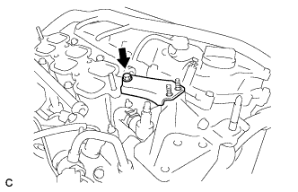
Remove the bolt and No. 2 engine mounting stay RH.
-
-
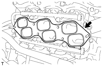
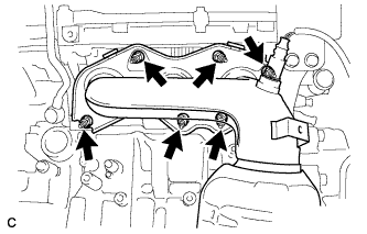
REMOVE INTAKE MANIFOLD
-
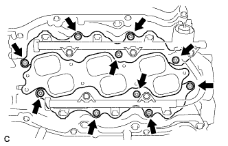
Uniformly loosen and remove the 6 bolts and 4 nuts.
-
Remove the intake manifold and 2 gaskets.
-
-
REMOVE EXHAUST MANIFOLD SUB-ASSEMBLY RH
-
Uniformly loosen and remove the 6 nuts.
-
Remove the exhaust manifold sub-assembly RH and gasket.
-
-
REMOVE NO. 2 ENGINE OIL LEVEL DIPSTICK GUIDE
-
Remove the engine oil level dipstick.
-
Remove the bolt and No. 2 engine oil level dipstick guide.
-
Remove the O-ring from the No. 2 engine oil level dipstick guide.
-
-
REMOVE NO. 2 MANIFOLD STAY
-
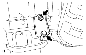
Remove the bolt, nut and No. 2 manifold stay.
-
-
REMOVE NO. 2 EXHAUST MANIFOLD HEAT INSULATOR
-
Disconnect the air fuel ratio sensor connector (for Bank 2 Sensor 1).
-
Disconnect the sensor wire from the radiator pipe clamp.
-
Remove the 3 bolts and No. 2 exhaust manifold heat insulator.
-
-
REMOVE EXHAUST MANIFOLD SUB-ASSEMBLY LH
-
Uniformly loosen and remove the 6 nuts.
-
Remove the exhaust manifold sub-assembly LH and gasket.
-
-
REMOVE V-RIBBED BELT TENSIONER ASSEMBLY
-
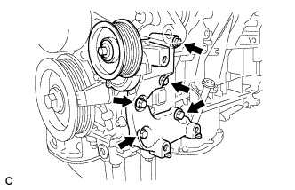
Remove the 5 bolts and V-ribbed belt tensioner assembly.
-
-
REMOVE NO. 2 TIMING GEAR COVER
-
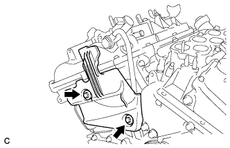
Remove the 2 bolts and No. 2 timing gear cover.
-
-
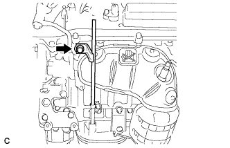
REMOVE WATER PUMP PULLEY
-
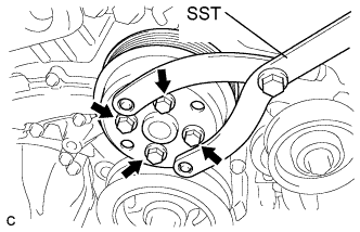
Using SST, hold the water pump pulley.
- SST
- 09960-10010 ( 09962-01000, 09963-00700 )
-
Remove the 4 bolts and water pump pulley.
-
-
REMOVE RADIO SETTING CONDENSER
-
Remove the 2 bolts and 2 radio setting condensers.
-
-
REMOVE NO. 1 VACUUM SWITCHING VALVE
-
Remove the bolt and No. 1 vacuum switching valve.
-
-
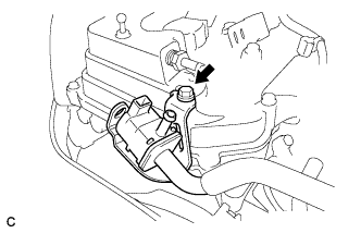
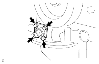
REMOVE ENGINE OIL PRESSURE SWITCH ASSEMBLY
-
Using a 24 mm deep socket wrench, remove the engine oil pressure switch assembly.
-
-
REMOVE SENSOR WIRE
-
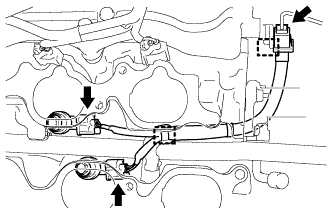
Disconnect the 2 knock control sensor connectors and knock control sensor wire connector.
-
Disconnect the 2 clamps and remove the knock control sensor wire from the engine assembly.
-
-
REMOVE KNOCK CONTROL SENSOR
-
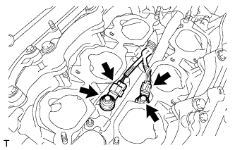
Disconnect the 2 knock control sensor connectors.
-
Remove the 2 bolts and 2 knock control sensors.
-
-
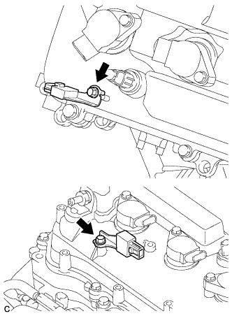
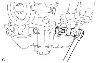
REMOVE ENGINE COOLANT TEMPERATURE SENSOR
-
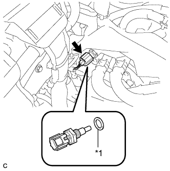
Text in Illustration *1 Gasket Disconnect the engine coolant temperature sensor connector.
-
Remove the engine coolant temperature sensor and gasket.
-
-
REMOVE ENGINE OIL LEVEL SENSOR
-
Remove the 4 bolts and engine oil level sensor.
-