ENGINE ASSEMBLY REMOVAL

-
PRECAUTION
Note
After turning the power switch off, waiting time may be required before disconnecting the cable from the negative (-) battery terminal. Therefore, make sure to read the disconnecting the cable from the negative (-) battery terminal notice before proceeding with work Click here.
-
PRECAUTION (w/ Air Suspension)
CAUTION:
Be sure to read Precaution thoroughly before servicing Click here.
-
REMOVE ENGINE ROOM SIDE COVER LH
-
Remove the 4 clips and engine room side cover LH.
-
-
REMOVE ENGINE ROOM SIDE COVER
-
Remove the 4 clips and engine room side cover.
-
-
REMOVE COOL AIR INTAKE DUCT SEAL
-
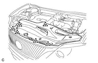
Remove the 6 clips and cool air intake duct seal.
-
-
RECOVER REFRIGERANT FROM REFRIGERATION SYSTEM
-
Turn the A/C switch on.
-
Operate the A/C with the setting temperature at 25°C (77°F) and the blower level at LO for 10 minutes to circulate the refrigerant. This causes most of the compressor oil from the various components of the A/C system to collect in the A/C compressor.
-
Turn the power switch off.
-
Recover the refrigerant from the A/C system using a refrigerant recovery unit.
-
-
DISCHARGE FUEL SYSTEM PRESSURE
Tech Tips
-
ALIGN FRONT WHEELS FACING STRAIGHT AHEAD
-
REMOVE REAR DECK FLOOR BOX
-
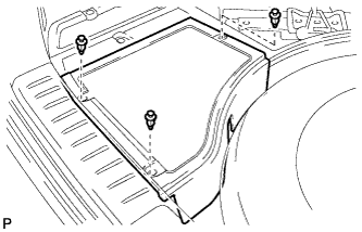
Remove the 3 clips and the rear deck floor box.
-
-
DISCONNECT CABLE FROM NEGATIVE BATTERY TERMINAL
Note
When disconnecting the cable, some systems need to be initialized after the cable is reconnected Click here.
-
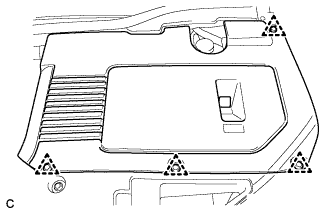
REMOVE BATTERY SERVICE HOLE COVER
-
Disengage the 2 clips and 2 guides, and remove the battery service hole cover.
Tech Tips
Because these are 2-piece clips, one side will remain in the bracket when they are being removed.
-
-
REMOVE SERVICE PLUG GRIP
CAUTION:
-
Remove the service plug grip to interrupt a high voltage circuit at the time of the check.
-
Keep the removed service plug grip in your pocket to prevent other technicians from accidentally reconnecting it while you are servicing the vehicle.
-
All the high voltage wiring connectors are orange colored.
-
Wear insulated gloves. Remove the service plug grip after sliding the lever of the service plug grip.
CAUTION:
-
Keep the removed service plug grip in your pocket to prevent other technicians from accidentally reconnecting it while you are servicing the vehicle.
-
After disconnecting the service plug grip, wait for at least 10 minutes before touching any of the high-voltage connectors or terminals.
Tech Tips
Waiting for at least 10 minutes is required to discharge the high-voltage capacitor inside the inverter with converter assembly.
-
-
-
REMOVE FRONT WHEEL
-
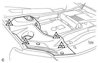
REMOVE NO. 1 ENGINE UNDER COVER
-
REMOVE NO. 2 ENGINE UNDER COVER
-
REMOVE FRONT FENDER LINER LH
-
REMOVE FRONT FENDER LINER RH
-
REMOVE FRONT FENDER APRON SEAL LH
-
REMOVE FRONT FENDER APRON SEAL RH
-
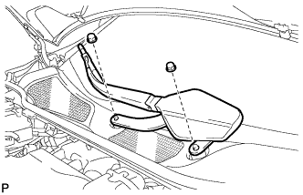
REMOVE SUSPENSION TOWER DAMPER (w/ Suspension Tower Damper)
-
Remove the 4 nuts and the suspension tower damper from the vehicle.
-
-
DRAIN ENGINE OIL
-
Remove the oil filler cap.
-
Remove the oil pan drain plug and gasket, and drain the oil into a container.
-
Clean the oil pan drain plug.
-
Install the oil pan drain plug with a new gasket.
- Torque:
- 40 N*m { 408 kgf*cm, 30 ft.*lbf }
-
-
DRAIN COOLANT (for Engine)
Note
Do not remove the radiator cap, cylinder block drain cock plugs and radiator drain cock plug while the engine and radiator are still hot. Pressurized hot engine coolant and steam may be released and cause serious burns.
-
Loosen the radiator drain cock plug and drain the coolant.
Tech Tips
Collect the coolant in a container and dispose of it according to the regulations in your area.
-
Remove the radiator cap from the radiator assembly.
-
Loosen the 2 cylinder block drain cock plugs.
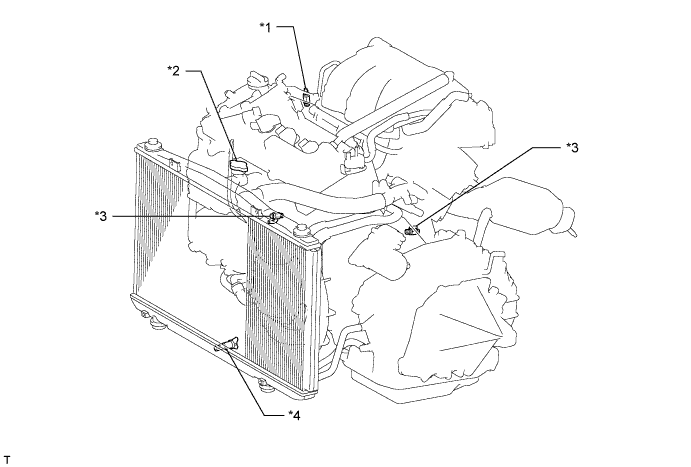
Text in Illustration *1 Air Drain Cock Plug *2 Radiator Cap *3 Cylinder Block Drain Cock Plug *4 Radiator Drain Cock Plug
-
-
DRAIN COOLANT (for Inverter)
Note
-
Do not reuse the drained coolant because it may contain foreign objects.
-
Collect the drained coolant and measure its volume to establish a benchmark. When adding coolant, make sure to add more coolant than the measured amount.
-
Remove the inverter reserve tank cap.
CAUTION:
To avoid the danger of being burned, do not remove the inverter reserve tank cap while the coolant for the inverter is still hot.
-
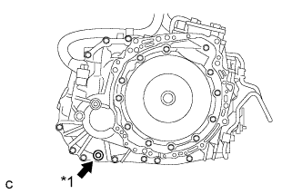
Loosen the drain plug indicated in the illustration and drain the coolant.
CAUTION:
Use caution when handling coolant immediately after driving or in summer because it may be hot.
-
Tighten the plug.
-
-
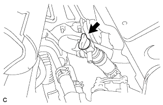
DRAIN HYBRID TRANSAXLE FLUID
-
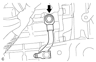
Text in Illustration *1 Filler Plug Using a hexagon socket wrench 10 mm, remove the filler plug and gasket.
-
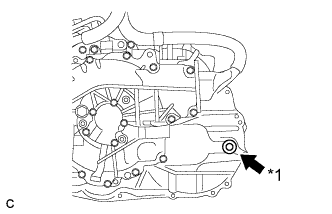
Text in Illustration *1 Drain Plug Using a hexagon socket wrench 10 mm, remove the drain plug and gasket.
-
Using a hexagon socket wrench 10 mm, install the drain plug and a new gasket.
- Torque:
- 39 N*m { 398 kgf*cm, 29 ft.*lbf }
-
-
REMOVE FRONT FENDER TOP REINFORCEMENT SUB-ASSEMBLY LH
-
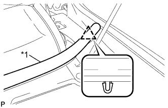
Text in Illustration *1 Hood to Cowl Top Seal Disengage the clip and the hood to cowl top seal from the front fender top reinforcement sub-assembly LH.
-
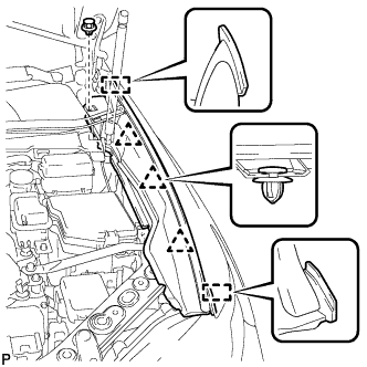
Remove the clip.
-
Disengage the 3 clips and 2 guides, and remove the front fender top reinforcement sub-assembly LH.
-
-
REMOVE FRONT FENDER TOP REINFORCEMENT SUB-ASSEMBLY RH
Tech Tips
Use the same procedure for the RH side and LH side.
-
REMOVE FRONT FENDER TO COWL SIDE SEAL LH
-
Text in Illustration *1 Double-sided Tape Disengage the 2 claws and remove the front fender to cowl side seal LH.
-
-
REMOVE FRONT FENDER TO COWL SIDE SEAL RH
Tech Tips
Use the same procedure for the RH side and LH side.
-
REMOVE FRONT WIPER ARM HEAD CAP
-
Text in Illustration *1 Protective Tape Using a screwdriver, disengage the 3 claws and remove the front wiper arm head cap.
Tech Tips
Tape the screwdriver tip before use.
-
-
REMOVE FRONT WIPER ARM AND BLADE ASSEMBLY LH
-
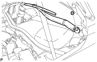
Remove the nut and the front wiper arm and blade assembly LH.
-
-
REMOVE FRONT WIPER ARM AND BLADE ASSEMBLY RH
-
Remove the 2 nuts and the front wiper arm and blade assembly RH.
-
-
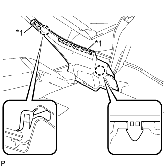
REMOVE COWL TOP VENTILATOR LOUVER SUB-ASSEMBLY
-
Remove the 2 clips.
-
Disengage the 6 claws and guide <A>.
-
Disengage the 10 guides and pull out the cowl top ventilator louver sub-assembly as shown in the illustration.
-
-
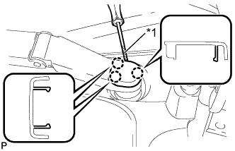
REMOVE WINDSHIELD WIPER MOTOR AND LINK ASSEMBLY
-
Operate the wiper and stop the windshield wiper motor at the automatic stop position.
-
w/o Deicer:
-
Disconnect the connector.
-
Disengage the clamp.
-
-
w/ Deicer:
-
Disconnect the 2 connectors.
-
Disengage the clamp.
-
-
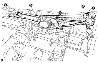
Remove the 5 bolts and the windshield wiper motor and link assembly.
Note
Be careful not to damage the windshield when removing the windshield wiper motor and link assembly.
-
-
REMOVE FRONT SHOCK ABSORBER CAP LH (w/ Air Suspension)
-
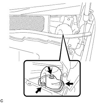
Remove the 3 nuts and front shock absorber cap.
-
-
REMOVE FRONT SHOCK ABSORBER CAP RH (w/ Air Suspension)
Tech Tips
Perform the same procedure as for the LH side.
-
REMOVE OUTER COWL TOP PANEL SUB-ASSEMBLY (for RHD)
-
Disconnect the connector (w/ Windshield Deicer).
-
Disengage the grommet and clamp, and separate the wire harness.
-
Remove the 6 nuts, 4 bolts and outer cowl top panel sub-assembly.
-
-
REMOVE OUTER COWL TOP PANEL SUB-ASSEMBLY (for LHD)
-
Disconnect the connector (w/ Windshield Deicer).
-
Disengage the grommet and clamp, and separate the wire harness.
-
Remove the 6 nuts, 4 bolts and outer cowl top panel sub-assembly.
-
-
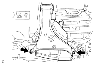
REMOVE INTAKE AIR RESONATOR SUB-ASSEMBLY
-
Remove the 3 clamps and Disconnect the water hose from the intake air resonator sub-assembly.
-
Remove the 2 bolts and intake air resonator sub-assembly from the inverter with converter assembly.
-
-
REMOVE INLET NO. 2 AIR CLEANER
-
Remove the 2 bolts and inlet No. 2 air cleaner.
-
-
REMOVE V-BANK COVER SUB-ASSEMBLY
-
Hold the front of the V-bank cover sub-assembly and raise it to disengage the 2 retainers on the front of the V-bank cover sub-assembly. Continue to raise the V-bank cover sub-assembly to disengage the 2 retainers on the rear of the V-bank cover sub-assembly and remove the V-bank cover sub-assembly.
Note
Attempting to disengage both front and rear retainers at the same time may cause the V-bank cover sub-assembly to break.
-
-
REMOVE INLET NO. 1 AIR CLEANER
-
Disconnect the No. 1 fuel vapor feed hose from the inlet No. 1 air cleaner.
-
Remove the bolt and inlet No. 1 air cleaner.
-
-
REMOVE AIR CLEANER ASSEMBLY WITH HOSE
-
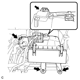
Disconnect the air flow meter connector and harness clamp.
-
Disconnect the No. 1 fuel vapor feed hose from the air cleaner hose.
-
Loosen the band and disconnect the air cleaner hose.
-
Remove the 2 bolts and air cleaner assembly with hose.
-
-
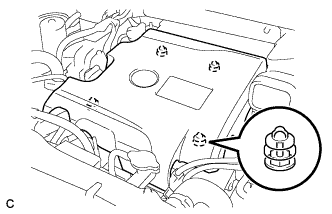
REMOVE NO. 3 INVERTER BRACKET
-
Disconnect the water hose clamp from the No. 3 inverter bracket.
-
Remove the bolt, nut and No. 3 inverter bracket.
-
-
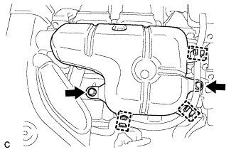
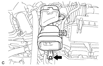
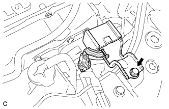
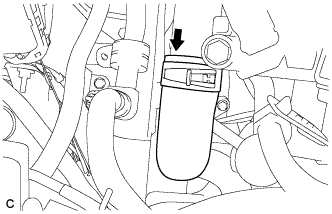
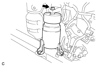
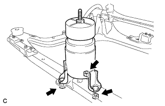
REMOVE INVERTER RESERVE TANK ASSEMBLY
-
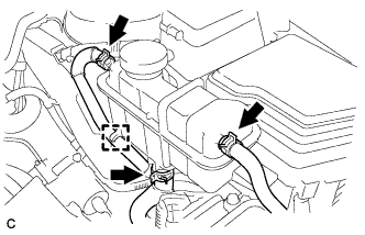
Disconnect the hose from the inverter reserve tank.
-
Slide the 3 hose clamps, and disconnect the 3 water hoses from the inverter reserve tank assembly.
-
Remove the bolt, nut and inverter reserve tank assembly.
-
-
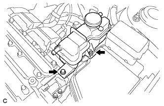
REMOVE NO. 1 INVERTER RESERVE TANK BRACKET
-
Remove the 2 bolts and No. 1 inverter reserve tank bracket.
-
-
REMOVE INVERTER TERMINAL COVER
CAUTION:
Wear insulating gloves.
-
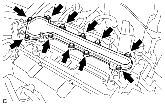
Remove the 11 bolts and inverter terminal cover.
Note
Make sure to pull the inverter cover straight up, as a connector is connected to the bottom of the cover.
-
-
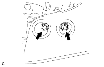
CHECK TERMINAL VOLTAGE
CAUTION:
Wear insulating gloves.
Note
-
Insulate the removed terminals with insulating tape.
-
Do not allow any foreign objects or water to enter the inverter with converter assembly.
-
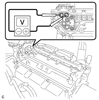
Using a voltmeter, measure the voltage between the 2 terminals.
Standard voltage 0 V Tech Tips
Use a measuring range of DC 750 V or more on the voltmeter.
-
-
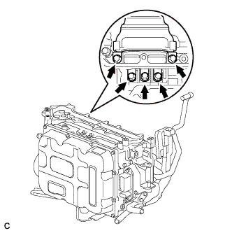
DISCONNECT NO. 4 ENGINE WIRE
CAUTION:
Wear insulating gloves.
Note
-
Insulate the removed terminals with insulating tape.
-
Cover the hole where the cable was connected with tape or equivalent (non-residue type) to prevent entry of foreign matter.
-
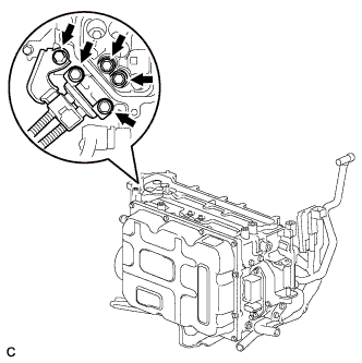
Remove the 5 bolts, and disconnect the No. 4 engine wire (high voltage cables of the air conditioning) from the inverter with converter assembly.
-
-
DISCONNECT NO. 3 WIRE FRAME (for AWD)
CAUTION:
Wear insulating gloves.
Note
-
Insulate the removed terminals with insulating tape.
-
Cover the hole where the cable was connected with tape or equivalent (non-residue type) to prevent entry of foreign matter.
-
Remove the 5 bolts, and disconnect the No. 3 wire frame (high voltage cables of the rear motor (MGR)) from the inverter with converter assembly.
-
Disconnect the harness clamp.
-
-
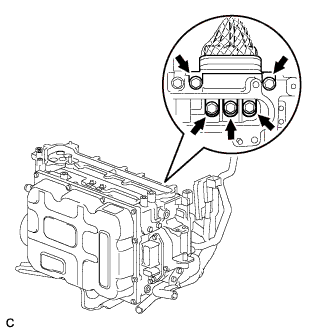
DISCONNECT HIGH VOLTAGE CABLE OF FRONT MOTOR
CAUTION:
Wear insulating gloves.
Note
-
Insulate the removed terminals with insulating tape.
-
Cover the hole where the cable was connected with tape or equivalent (non-residue type) to prevent entry of foreign matter.
-
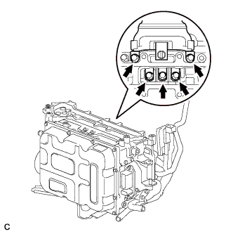
Remove the 5 bolts, and disconnect the high voltage cables of the generator (MG1) from the inverter with converter assembly.
-
Remove the 5 bolts, and disconnect the high voltage cables of the motor (MG2) from the inverter with converter assembly.
-
-
DISCONNECT NO. 3 WIRE FRAME
CAUTION:
Wear insulating gloves.
Note
-
Insulate the removed terminals with insulating tape.
-
Cover the hole where the cable was connected with tape or equivalent (non-residue type) to prevent entry of foreign matter.
-
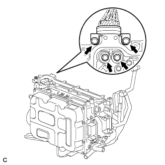
Remove the 4 bolts, and disconnect the No. 3 wire frame (high voltage cables of the hybrid battery) from the inverter with converter assembly.
-
Disconnect the 3 harness clamps.
-
-
INSTALL INVERTER TERMINAL COVER
-
Temporarily install the inverter cover with the 11 bolts to prevent any foreign objects or water from entering the inverter with converter assembly.
-
-
REMOVE NO. 6 INVERTER BRACKET (w/ Bracket)
-
Remove the 2 bolts and No. 6 inverter bracket.
-
-
SEPARATE RELAY BLOCK SUB-ASSEMBLY
-
Disconnect the clamp, and release the relay block sub-assembly.
-
-
DISCONNECT MG ECU CONNECTOR
CAUTION:
Wear insulating gloves.
Note
-
Insulate the removed terminals with insulating tape.
-
Do not allow any foreign objects or water to enter the inverter with converter assembly.
-
To prevent damage due to static electricity, do not touch the terminals of the disconnected connectors.
-
Raise the lock lever and disconnect the inverter with converter connector.
-
Disconnect the connector from the inverter with converter assembly.
-
-
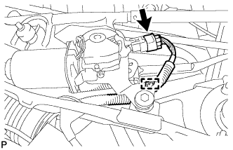
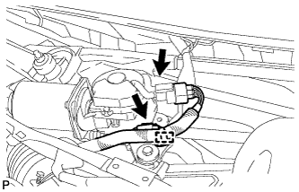
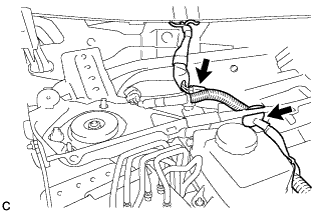
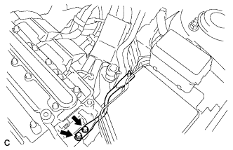
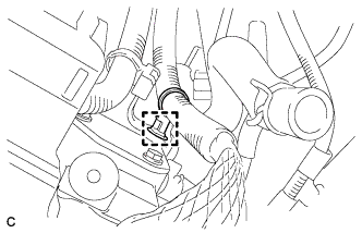
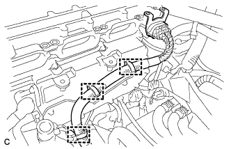
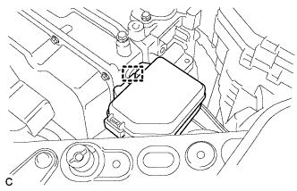
DISCONNECT WATER HOSE
-
Slide the 2 clamps, and disconnect the 2 water hoses from the inverter with converter assembly.
-
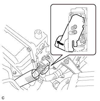
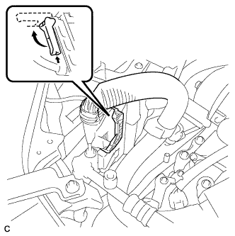
Text in Illustration *1 Retainer Release the retainer and disconnect the water hose from the inverter with converter assembly.
-
Disconnect the coolant hose from the inverter with converter assembly. Put a piece of cloth in the pipe and in the disconnected hose or cover the pipe and hose with plastic bags as shown in the illustration in order to prevent coolant from spilling around the inverter with converter assembly.
-
-
DISCONNECT NO. 2 ENGINE ROOM WIRE
-
Remove the relay block cover.
-
Remove the nut from the No. 2 engine room wire.
-
Release the claw, and disconnect the No. 2 engine room wire.
-
Disconnect the clamp.
-
-
REMOVE NO. 4 INVERTER BRACKET
-
Remove the bolt, nut and No. 4 inverter bracket.
-
-
SEPARATE RADIATOR RESERVE TANK ASSEMBLY
-
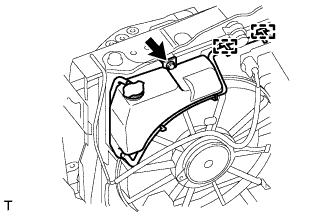
Disconnect the 2 clamps and remove the bolt and radiator reserve tank from the radiator.
-
-
SEPARATE CONDENSER
-
Remove the bolt, and separate the condenser.
-
-
REMOVE INVERTER WITH CONVERTER ASSEMBLY
CAUTION:
Wear insulating gloves.
-
Remove the 2 bolts, nut and inverter with converter assembly.
Note
-
Since the inverter with converter assembly is very heavy, 2 people are needed to remove the inverter with converter assembly. When removing the inverter with converter assembly, do not damage the parts around it.
-
To prevent damage, do not hold the inverter with converter assembly by the connectors.
-
To prevent damage due to static electricity, do not touch the terminals of the disconnected connectors.
-
-
-
REMOVE INVERTER TRAY BRACKET SUB-ASSEMBLY
-
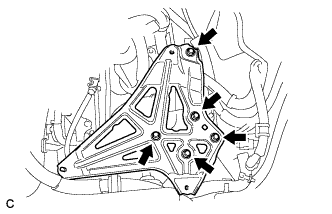
Remove the 5 bolts and inverter tray bracket sub-assembly.
-
-
DISCONNECT NO. 1 MOTOR COOLING HOSE
-
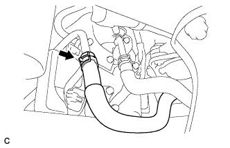
Disconnect the No. 1 motor cooling hose.
-
-
DISCONNECT NO. 3 MOTOR COOLING HOSE
-
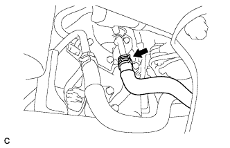
Disconnect the No. 3 motor cooling hose.
-
-
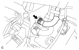
DISCONNECT NO. 1 RADIATOR HOSE
-
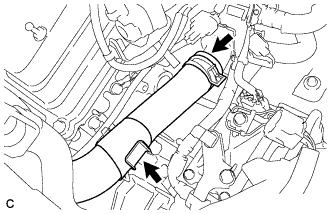
Separate the No. 1 radiator hose from the radiator pipe clamp.
-
Disconnect the No. 1 radiator hose.
-
-
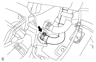
DISCONNECT NO. 2 RADIATOR HOSE
Disconnect the No. 2 radiator hose.
-
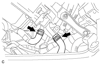
DISCONNECT INLET HEATER WATER HOSE
-
Disconnect the inlet heater water hose.
-
-
DISCONNECT OUTLET HEATER WATER HOSE
-
Disconnect the outlet heater water hose.
-
-
DISCONNECT NO. 1 FUEL VAPOR FEED HOSE
-
Disconnect the No. 1 fuel vapor feed hose.
-
-
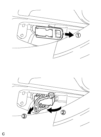
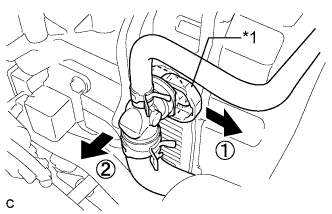
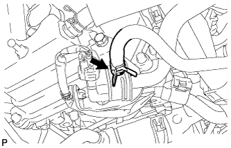
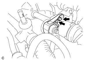
DISCONNECT TRANSMISSION CONTROL CABLE ASSEMBLY
-
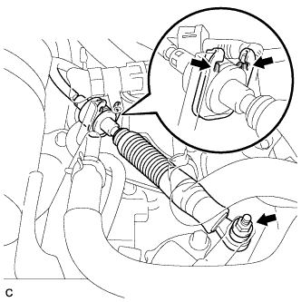
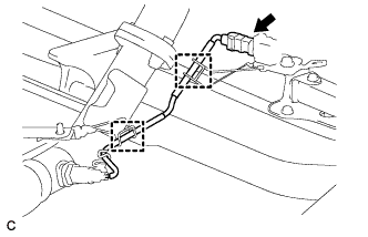
Remove the nut from the control shaft lever.
-
Using a screwdriver, disengage the claw and disconnect the transmission control cable assembly with clip from the control cable bracket.
-
Remove the clip from the transmission control cable assembly.
-
Disconnect the transmission control cable assembly from the 3 control cable brackets.
-
-
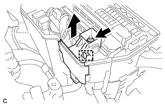
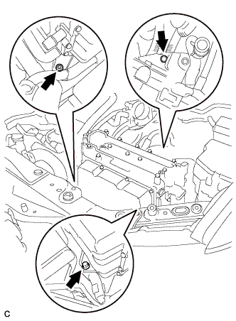
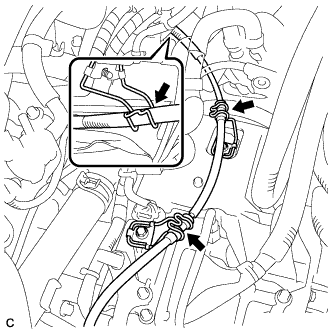
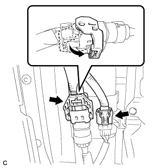
DISCONNECT ENGINE WIRE
-
Remove the relay block cover.
-
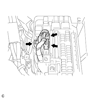
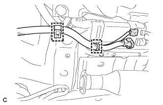
Disconnect the 3 connectors.
-
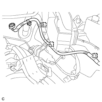
Disconnect the 3 clamps.
-
Remove the bolt and disconnect the earth wire from the hybrid vehicle transaxle assembly.
-
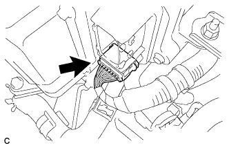
Pull up the lever to disconnect the ECM connector.
-
-
REMOVE NO. 2 ENGINE MOUNTING STAY RH
-
Remove the bolt, 2 nuts and No. 2 engine mounting stay RH.
-
-
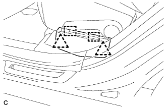
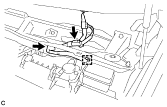
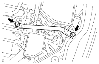
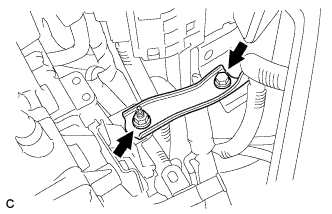
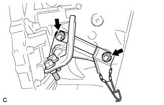
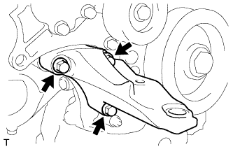
REMOVE ENGINE MOVING CONTROL ROD BRACKET
-
Remove the 4 bolts and engine moving control rod with engine mounting control rod bracket.
-
-
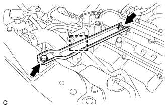
REMOVE NO. 3 ENGINE MOUNTING STAY RH
Tech Tips
Perform this procedure only when replacement of the engine moving control rod or No. 3 engine moving stay RH is necessary.
-
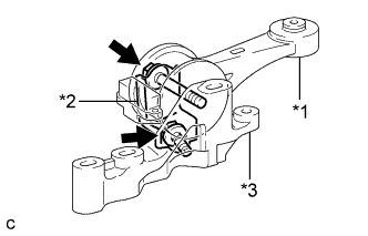
Text in Illustration *1 Engine moving control rod *2 No. 3 engine moving stay RH *3 Engine moving control rod bracket Remove the 2 bolts, engine moving control rod and No. 3 engine moving stay RH from the engine moving control rod bracket.
-
-
DISCONNECT DISCHARGE HOSE SUB-ASSEMBLY
-
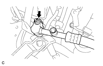
Remove the nut and disconnect the discharge hose sub-assembly.
Note
Seal the openings of the disconnected parts using vinyl tape to prevent entry of moisture and foreign matter.
-
-
DISCONNECT SUCTION HOSE SUB-ASSEMBLY
-
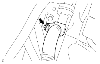
Remove the nut and disconnect the suction hose sub-assembly.
Note
Seal the openings of the disconnected parts using vinyl tape to prevent entry of moisture and foreign matter.
-
-
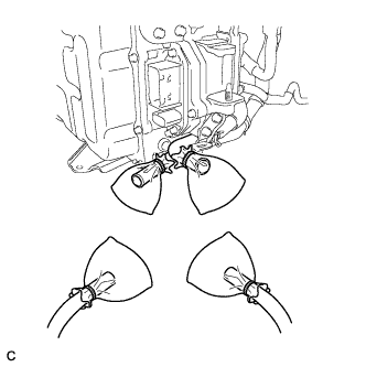
DISCONNECT FUEL MAIN TUBE
-
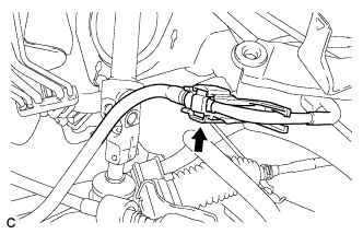
Remove the No. 1 fuel pipe clamp.
-
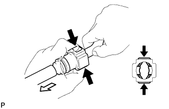
Disconnect the connector from the pipe by hand. When the connector and the pipe are stuck, push in and pull on the connector to release it. Pull the connector out of the pipe carefully.
Note
-
Check for any dirt and foreign matter contamination in the pipe and around the connector. Clean if necessary. Foreign matter may damage the O-rings or cause leaks in the seal between the pipe and connector.
-
Do not use any tools to separate the pipe and connector.
-
Do not forcefully bend or twist the nylon tube.
-
Check for any dirt and foreign matter on the pipe seal surface. Clean if necessary.
-
Put the pipe and connector ends in plastic bags to prevent damage and dirt contamination.
-
If the pipe and connector are stuck together, pinch the tube between your fingers and turn it carefully to free it. Then disconnect the hose.
-
-
-
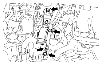
REMOVE FRONT NO. 3 EXHAUST PIPE SUB-ASSEMBLY
-
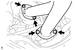
Remove the 2 bolts, 2 nuts and front No. 3 exhaust pipe sub-assembly.
-
Remove the 2 gaskets from the front No. 3 exhaust pipe sub-assembly.
-
-
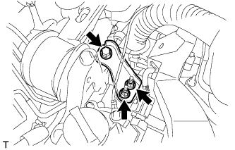
REMOVE FRONT EXHAUST PIPE ASSEMBLY
-
Disconnect the 2 clamps and No. 2 oxygen sensor connector (for Bank 2 Sensor 2).
-
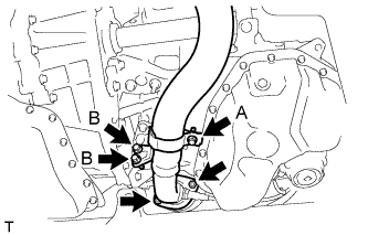
Loosen the bolt (A).
-
Remove the 2 bolts (B), 2 nuts and front exhaust pipe assembly.
-
Remove the gasket from the front exhaust pipe assembly.
-
-
SECURE STEERING WHEEL
-
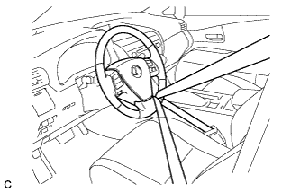
Secure the steering wheel with the seat belt in order to prevent it from rotating.
Tech Tips
This operation is necessary to prevent damage to the spiral cable.
-
-
SEPARATE STEERING INTERMEDIATE SHAFT ASSEMBLY
-
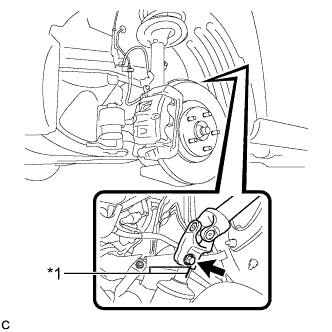
Text in Illustration *1 Matchmark Put matchmarks on the steering intermediate shaft assembly and steering link assembly.
Note
Do not separate the steering intermediate shaft assembly from the steering link assembly.
-
Remove the bolt.
-
Separate the steering intermediate shaft assembly from the steering link assembly.
-
-
SEPARATE HEIGHT CONTROL SENSOR LINK SUB-ASSEMBLY (w/ Air Suspension)
-
Remove the 2 nuts and separate the height control sensor link sub-assembly LH and RH from the front lower suspension arm LH and RH.
-
-
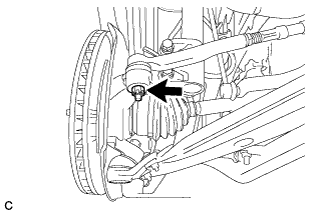
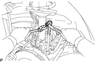
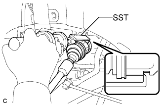
REMOVE FRONT AXLE SHAFT NUT LH
-
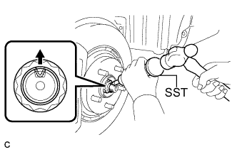
Using SST and a hammer, release the staked part of the front axle shaft nut.
- SST
- 09930-00010
Note
Loosen the staked part of the nut completely, otherwise the threads of the drive shaft may be damaged.
-
While applying the brakes, remove the front axle shaft nut.
-
-
REMOVE FRONT AXLE SHAFT NUT RH
Tech Tips
Perform the same procedure as for the LH side.
-
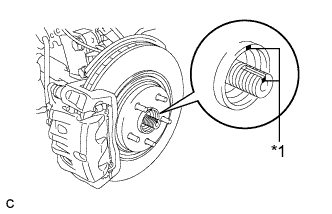
SEPARATE FRONT SPEED SENSOR LH
-
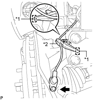
Text in Illustration *1 Hole *2 Resin Clamp Remove the bolt and resin clamp, and separate the front speed sensor.
Note
-
Be sure to completely separate the front speed sensor from the front shock absorber with coil spring.
-
Be careful not to damage the front speed sensor.
-
Clean the speed sensor installation hole and the contact surfaces every time the speed sensor is removed.
-
-
-
SEPARATE FRONT SPEED SENSOR RH
Tech Tips
Perform the same procedure as for the LH side.
-
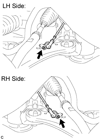
SEPARATE TIE ROD ASSEMBLY LH
-
Remove the cotter pin and nut.
-
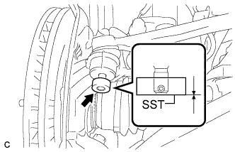
Install SST to the tie rod end.
- SST
- 09960-20010 ( 09961-02060 )
Note
Make sure that the upper ends of the tie rod end and SST are aligned.
-
Using SST, separate the tie rod end from the steering knuckle.
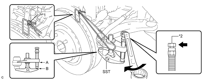
Text in Illustration *1 Tie the string without allowing for any slack. *2 Place the wrench here. - SST
- 09960-20010 ( 09961-02010 )
Note
-
When securing SST to the steering knuckle, be sure to tighten SST using a string to prevent it from falling.
-
Install SST so that A and B are parallel.
-
Be sure to place a wrench on the part indicated in the illustration.
-
Do not damage the front disc brake dust cover.
-
Do not damage the ball joint dust cover.
-
Do not damage the steering knuckle.
-
-
SEPARATE TIE ROD ASSEMBLY RH
Tech Tips
Perform the same procedure as for the LH side.
-
SEPARATE FRONT STABILIZER LINK ASSEMBLY LH
-
Remove the nut and separate the front stabilizer link assembly from the front shock absorber.
Tech Tips
If the ball joint turns together with the nut, use a hexagon wrench (6 mm) to hold the stud bolt.
-
-
SEPARATE FRONT STABILIZER LINK ASSEMBLY RH
Tech Tips
Perform the same procedure as for the LH side.
-
SEPARATE FRONT LOWER SUSPENSION ARM LH
-
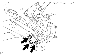
Remove the bolt and 2 nuts, and separate the front lower suspension arm from the lower ball joint.
-
-
SEPARATE FRONT LOWER SUSPENSION ARM RH
Tech Tips
Perform the same procedure as for the LH side.
-
SEPARATE FRONT DRIVE SHAFT ASSEMBLY LH
-
Text in Illustration *1 Matchmark Put matchmarks on the front drive shaft assembly and the front axle hub sub-assembly.
-
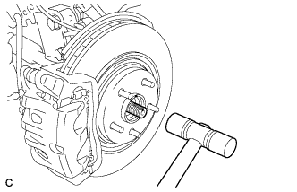
Using a plastic hammer, separate the front drive shaft assembly from the front axle assembly.
Note
Loosen the staked part of the front axle hub nut completely, otherwise the threads of the drive shaft may be damaged.
-
-
REMOVE FRONT DRIVE SHAFT ASSEMBLY LH
-
Using SST, remove the front drive shaft assembly LH.
- SST
- 09520-00031
- 09520-01010
Note
-
Be careful not to damage the drive shaft dust cover, boot or oil seal.
-
Be careful not to drop the drive shaft assembly.
-
-
REMOVE FRONT DRIVE SHAFT HOLE SNAP RING
-
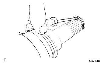
Using a screwdriver, remove the front drive shaft hole snap ring.
-
-
SEPARATE FRONT DRIVE SHAFT ASSEMBLY RH
Tech Tips
Perform the same procedure as for the LH side.
-
REMOVE FRONT DRIVE SHAFT ASSEMBLY RH
-
Remove the bearing bracket hole snap ring from the drive shaft bearing bracket.
-
Remove the bolt and front drive shaft assembly RH from the drive shaft bearing bracket.
Note
Do not damage the boot or oil seal.
-
-
REMOVE NO. 1 EXHAUST PIPE SUPPORT BRACKET
-
Remove the 2 nuts and No. 1 exhaust pipe support bracket.
-
-
REMOVE FLYWHEEL HOUSING UNDER COVER
-
Remove the 2 bolts and flywheel housing under cover.
-
-
REMOVE HEATER COVER (w/ Active Stabilizer System)
-
Disconnect the clamp.
-
Remove the 2 bolts and heater cover.
-
-
REMOVE ENGINE ASSEMBLY WITH TRANSAXLE
-
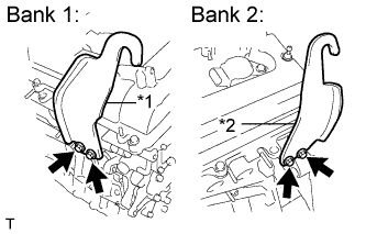
w/ Active Stabilizer System:
-
Disconnect the 2 front active stabilizer connectors.
-
Disconnect the 2 clamps.
-
-
Set an engine lifter.
Note
-
Install a height adjustment attachment and plate lift attachment onto the engine assembly with transaxle.
-
Securely support the engine assembly to prevent it from turning upside down until it is secured to an engine stand.
-
Do not perform any procedure while the engine assembly is suspended because doing so may cause the engine assembly to drop, resulting in injury. However, the engine assembly needs to be suspended when it is installed to or removed from an engine stand.
-
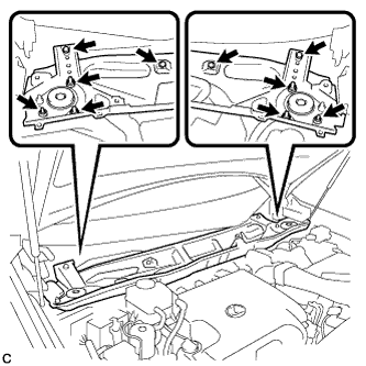
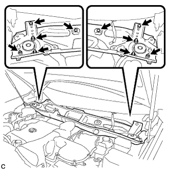
-
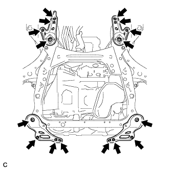
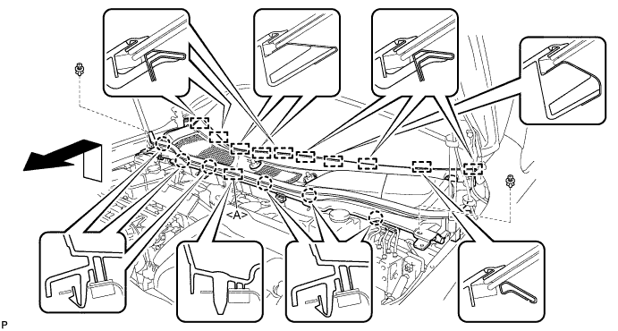
Remove the 6 bolts, 2 nuts and frame side rail plates RH and LH.
-
Remove the 6 bolts, 2 nuts and front suspension member rear braces RH and LH.
-
Operate the engine lifter, then remove the engine assembly from the vehicle.
Note
-
Make sure that the engine is clear of all wiring and hoses.
-
While lowering the engine from the vehicle, do not allow it to contact the vehicle.
-
-
Text in Illustration *1 No. 1 Engine Hanger *2 No. 2 Engine Hanger Install the No. 1 and No. 2 engine hangers with the 4 bolts.
- Torque:
- 33 N*m { 337 kgf*cm, 24 ft.*lbf }
Part No. Item Part No. No. 1 Engine Hanger 12281-31120 No. 2 Engine Hanger 12282-31100 Bolt 91671-10825 -
Attach the sling device to the engine hangers and chain block.
-
-
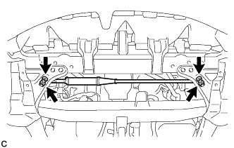
SEPARATE FRONT FRAME ASSEMBLY
-
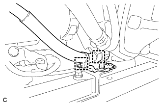
Disconnect the 2 clamps and engine wire from the front frame assembly.
-
Remove the bolt and HV transaxle mass damper.
-
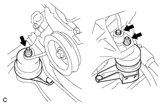
Remove the 2 nuts and separate the engine mounting insulators LH and RH.
-
Remove the bolt and separate the front engine mounting insulator.
-
Remove the 2 bolts and separate the rear engine mounting insulator.
Note
Do not remove the rear engine mounting insulator assembly through bolts. Doing so makes it difficult to install the rear engine mounting insulator assembly.
-
Remove the front frame assembly.
-
-
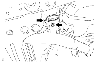
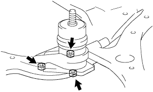
REMOVE FRONT ENGINE MOUNTING INSULATOR
-
Remove the 2 hole plugs.
-
Remove the 3 nuts and front engine mounting insulator.
Tech Tips
Perform this procedure only when replacement of the front engine mounting insulator is necessary.
-
-
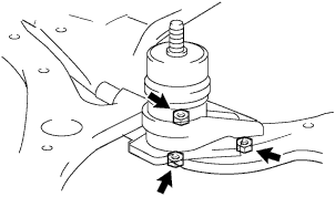
REMOVE REAR ENGINE MOUNTING INSULATOR ASSEMBLY
-
Remove the 2 hole plugs.
-
Remove the 2 nuts and rear engine mounting insulator assembly.
Note
Do not remove the rear engine mounting insulator assembly through bolts. Doing so makes it difficult to install the rear engine mounting insulator assembly.
Tech Tips
Perform this procedure only when replacement of the engine mounting insulator assembly is necessary.
-
-
REMOVE ENGINE MOUNTING INSULATOR LH
-
Remove the 2 hole plugs.
-
Remove the 3 nuts and engine mounting insulator LH.
Tech Tips
Perform this procedure only when replacement of the engine mounting insulator LH is necessary.
-
-
REMOVE ENGINE MOUNTING INSULATOR RH
-
Remove the 2 hole plugs.
-
Remove the 3 nuts and engine mounting insulator RH.
Tech Tips
Perform this procedure only when replacement of the engine mounting insulator RH is necessary.
-
-
REMOVE V-RIBBED BELT
-
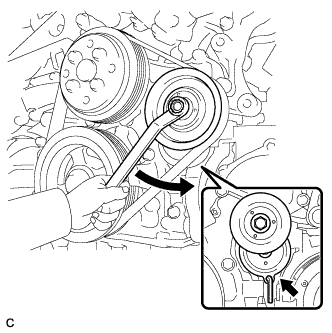
Release the V-ribbed belt tension by turning the V-ribbed belt tensioner counterclockwise, and remove the V-ribbed belt from the V-ribbed belt tensioner.
-
While turning the V-ribbed belt tensioner counterclockwise, align with its holes, and then insert a 5 mm bi-hexagon wrench into the holes to secure the V-ribbed belt tensioner.
-
-
REMOVE ELECTRIC INVERTER COMPRESSOR ASSEMBLY
-
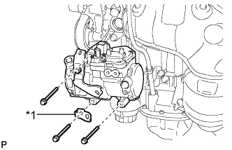
Text in Illustration *1 Bracket Remove the 3 bolts, bracket and electric inverter compressor assembly.
-
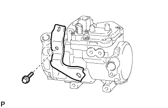
Remove the bolt and bracket from the electric inverter compressor assembly.
-
-
REMOVE RADIATOR PIPE CLAMP
-
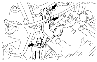
Separate the breather plug hose and sensor wire from the radiator pipe clamp.
-
Remove the bolt and radiator pipe clamp.
-
-
REMOVE ENGINE WIRE
-
Remove the engine wire from the engine with transaxle.
-
-
REMOVE MANIFOLD STAY
-
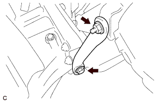
Remove the bolt, nut and manifold stay.
-
-
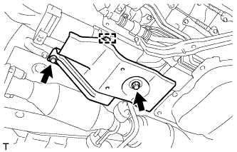
REMOVE NO. 3 AUTOMATIC TRANSMISSION CASE COVER
-
Remove the bolt and No. 3 transmission control cable bracket.
-
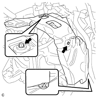
Remove the 2 bolts, clip and No. 3 automatic transmission case cover from the transaxle.
-
-
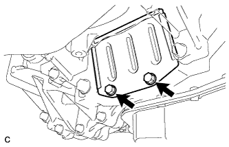
REMOVE AUTOMATIC TRANSMISSION CASE COVER
-
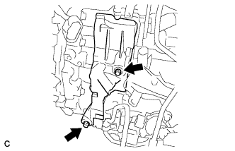
Remove the 2 bolts and automatic transmission case cover.
-
-
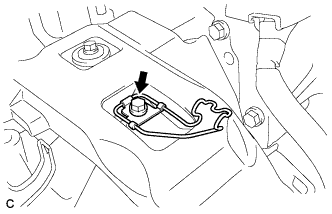
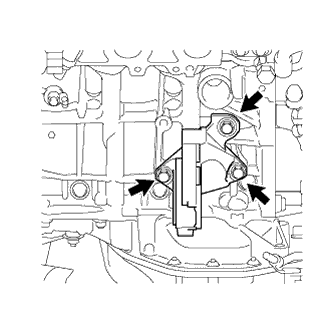
REMOVE FRONT ENGINE MOUNTING BRACKET
-
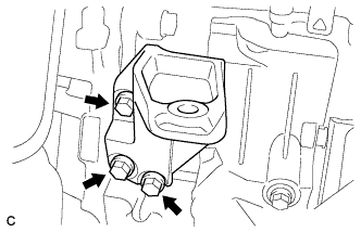
Remove the 3 bolts and front engine mounting bracket.
-
-
REMOVE HYBRID VEHICLE TRANSAXLE ASSEMBLY
-
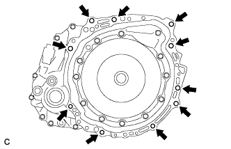
Remove the 10 bolts.
-
Separate and remove the hybrid vehicle transaxle assembly.
Note
Do not pry between the transaxle assembly and engine more than necessary to prevent the knock pins from being damaged.
-
-
REMOVE ENGINE MOUNTING BRACKET RH
-
Remove the 3 bolts and engine mounting bracket RH.
-
-
REMOVE REAR ENGINE MOUNTING BRACKET
-
Remove the 3 bolts and rear engine mounting bracket.
-
-
REMOVE TRANSMISSION INPUT DAMPER ASSEMBLY
-
Using SST, hold the crankshaft pulley.
- SST
- 09213-70011 ( 09213-70020 )
- 09330-00021
-
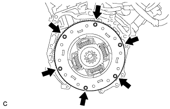
Remove the 6 bolts and transmission input damper assembly from the flywheel sub-assembly.
-
-
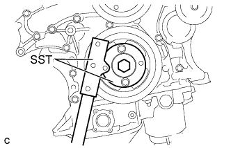
REMOVE FLYWHEEL SUB-ASSEMBLY
-
Using SST, hold the crankshaft pulley.
- SST
- 09213-70011 ( 09213-70020 )
- 09330-00021
-
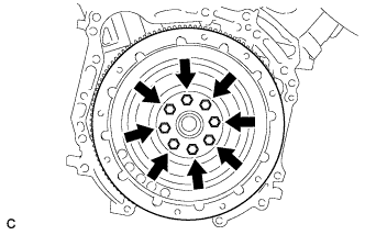
Remove the 8 bolts and flywheel sub-assembly.
-