HV BATTERY REMOVAL

-
PRECAUTION
Tech Tips
-
READ OUTPUT DTC
-
Check for DTCs Click here.
Note
Check for DTCs and confirm that P0AA6 (High voltage insulation is unusual) is not output before doing removal or installation inside the battery. If the DTC is output, perform troubleshooting first.
-
-
DISCONNECT CABLE FROM NEGATIVE AUXILIARY BATTERY TERMINAL
Note
When disconnecting the cable, some systems need to be initialized after the cable is reconnected Click here.
-
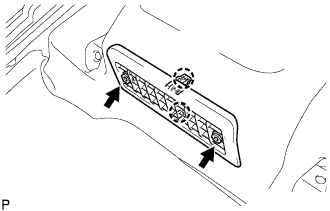
REMOVE BATTERY SERVICE HOLE COVER
-
Disengage the 2 clips and 2 guides, and remove the battery service hole cover.
Tech Tips
Because these are 2-piece clips, one side will remain in the bracket when they are being removed.
-
-
REMOVE SERVICE PLUG GRIP
CAUTION:
-
Remove the service plug grip to interrupt a high voltage circuit at the time of the check.
-
Keep the removed service plug grip in your pocket to prevent other technicians from accidentally reconnecting it while you are servicing the vehicle.
-
All the high voltage wiring connectors are orange colored.
-
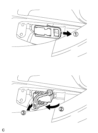
Wear insulated gloves. Remove the service plug grip after sliding the lever of the service plug grip.
CAUTION:
-
Keep the removed service plug grip in your pocket to prevent other technicians from accidentally reconnecting it while you are servicing the vehicle.
-
After disconnecting the service plug grip, wait for at least 10 minutes before touching any of the high-voltage connectors or terminals.
Tech Tips
Waiting for at least 10 minutes is required to discharge the high-voltage capacitor inside the inverter with converter assembly.
-
-
-
REMOVE ENGINE ROOM SIDE COVER LH
-
Remove the 4 clips and engine room side cover LH.
-
-
REMOVE ENGINE ROOM SIDE COVER
-
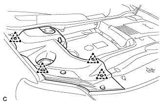
Remove the 4 clips and engine room side cover.
-
-
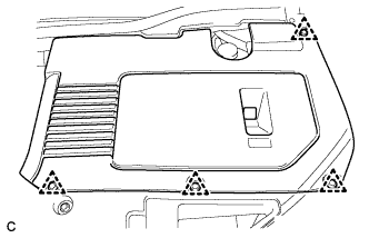
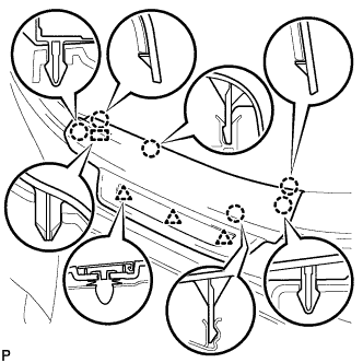
REMOVE COOL AIR INTAKE DUCT SEAL
-
Remove the 6 clips and cool air intake duct seal.
-
-
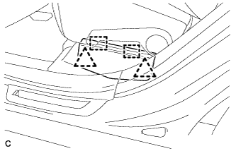
REMOVE INTAKE AIR RESONATOR SUB-ASSEMBLY
-
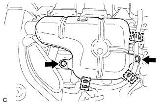
Remove the 3 clamps and Disconnect the water hose from the intake air resonator sub-assembly.
-
Remove the 2 bolts and intake air resonator sub-assembly from the inverter with converter assembly.
-
-
REMOVE INLET NO. 2 AIR CLEANER
-
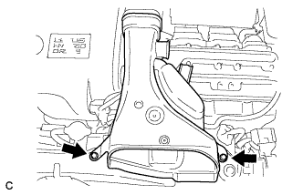
Remove the 2 bolts and inlet No. 2 air cleaner.
-
-
REMOVE INVERTER TERMINAL COVER
CAUTION:
Wear insulating gloves.
-
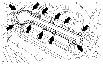
Remove the 11 bolts and inverter terminal cover.
Note
Make sure to pull the inverter cover straight up, as a connector is connected to the bottom of the cover.
-
-
CHECK TERMINAL VOLTAGE
CAUTION:
Wear insulating gloves.
Note
-
Insulate the removed terminals with insulating tape.
-
Do not allow any foreign objects or water to enter the inverter with converter assembly.
-
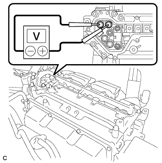
Using a voltmeter, measure the voltage between the 2 terminals.
Standard voltage 0 V Tech Tips
Use a measuring range of DC 750 V or more on the voltmeter.
-
-
INSTALL INVERTER TERMINAL COVER
-
Temporarily install the inverter cover with the 11 bolts to prevent any foreign objects or water from entering the inverter with converter assembly.
-
-
INSTALL INLET NO. 2 AIR CLEANER
-
Install the inlet No. 2 air cleaner with the 2 bolts.
- Torque:
- 8.0 N*m { 82 kgf*cm, 71 in.*lbf }
-
-
INSTALL INTAKE AIR RESONATOR SUB-ASSEMBLY
-
Install the intake air resonator sub-assembly with the 2 bolts.
- Torque:
- 8.0 N*m { 82 kgf*cm, 71 in.*lbf }
-
Connect the 3 water hose clamps to the intake air resonator sub-assembly.
-
-
INSTALL COOL AIR INTAKE DUCT SEAL
-
Install the cool air intake duct seal with the 6 clips.
-
-
INSTALL ENGINE ROOM SIDE COVER
-
Install the engine room side cover with the 4 clips.
-
-
INSTALL ENGINE ROOM SIDE COVER LH
-
Install the engine room side cover with the 4 clips.
-
-
REMOVE REAR NO. 1 SEAT ASSEMBLY (for LH Side)
Tech Tips
-
REMOVE REAR NO. 1 SEAT ASSEMBLY (for RH Side)
Tech Tips
-
REMOVE REAR DOOR SCUFF PLATE LH
-
Disengage the 6 claws, 3 clips and guide, and remove the rear door scuff plate LH.
-
-
REMOVE REAR DOOR SCUFF PLATE RH
Tech Tips
Perform the same procedure as for the LH side.
-
REMOVE REAR SEAT SIDE COVER LH
-
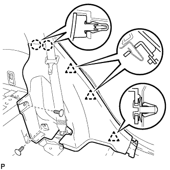
Remove the 2 clips.
-
Disengage the 2 claws and 3 clips, and remove the rear seat side cover LH.
Tech Tips
A part of the clip remains on the vehicle side.
-
-
REMOVE REAR SEAT SIDE COVER RH
Tech Tips
Perform the same procedure as for the LH side.
-
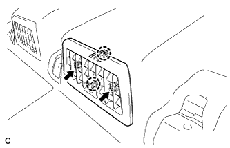
REMOVE AIR INTAKE COVER
-
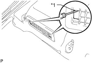
Remove the air intake cover LH.
-
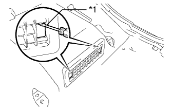
Text in Illustration *1 Protective Tape Release the claw by using a screwdriver with the tip taped, and remove its 2 hole covers.
-
Remove the 2 screws, then release the 2 claws and remove the air intake cover LH.
-
-
Remove the air intake cover CTR.
-
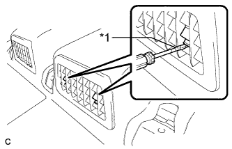
Text in Illustration *1 Protective Tape Release the claw by using a screwdriver with the tip taped, and remove its 2 hole covers.
-
Remove the 2 screws, then release the 2 claws and remove the center air intake cover.
-
-
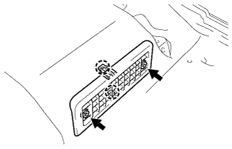
Remove the air intake cover RH.
-
Text in Illustration *1 Protective Tape Release the claw by using a screwdriver with its tip taped, and remove the 2 hole covers.
-
Remove the 2 screws, then release the 2 claws and remove the air intake cover RH.
-
-
-
SEPARATE FRONT FLOOR CARPET ASSEMBLY
-
Turn back the front floor carpet assembly.
-
-
REMOVE BATTERY CARRIER BRACKET
-
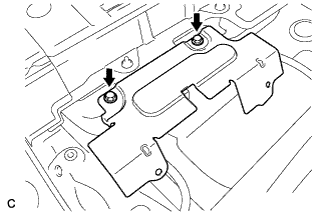
Remove the 2 bolts and battery carrier bracket.
-
-
REMOVE BATTERY CARRIER DUCT
-
Remove the 2 bolts and battery carrier duct LH.
-
Remove the 2 bolts and battery carrier duct CTR.
-
Remove the 2 bolts and battery carrier duct RH.
-
-
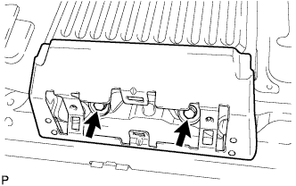
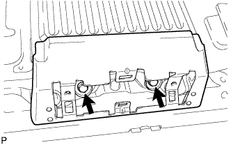
REMOVE NO. 1 BATTERY COVER LID
CAUTION:
Be sure to wear insulated gloves and protective goggles.
-
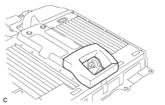
Using the service plug grip, remove the No. 1 battery cover lid.
Tech Tips
Insert the projection part of the service plug grip, and turn the button of the battery cover lock striker counterclockwise, and release the lock.
-
Remove the 2 bolts and battery service hole cover.
-
-
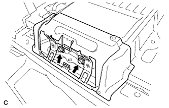
REMOVE BATTERY COVER SUB-ASSEMBLY
CAUTION:
Be sure to wear insulated gloves and protective goggles.
-
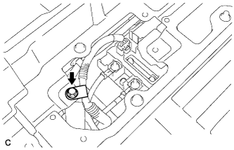
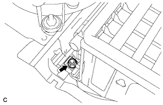
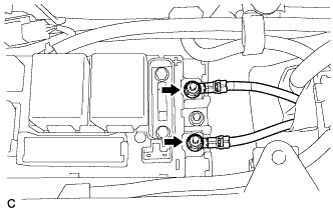
Remove the bolt and No. 3 wire frame from the battery cover sub-assembly.
-
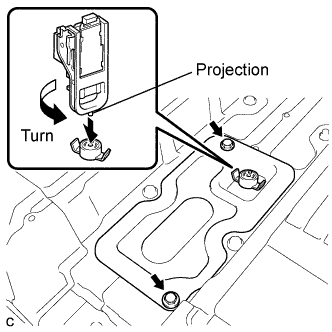
Using the service plug grip, remove the battery cover lock striker.
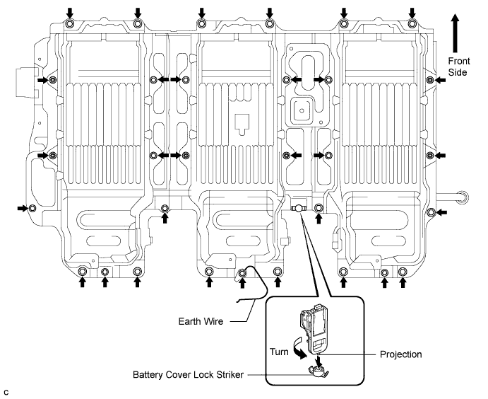
Tech Tips
Insert the projection part of the service plug grip, and turn the button of the battery cover lock striker counterclockwise to release the lock.
-
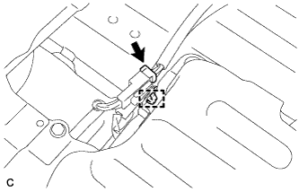
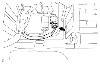
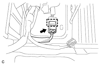
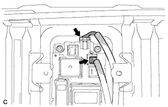
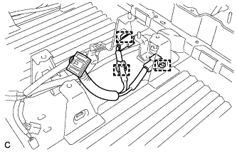
Disconnect the connector and clamp shown in the illustration.
-
Separate the 2 claws and clamp, and remove the indoor electrical key oscillator.
-
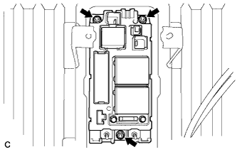
Remove the 25 bolts, 6 nuts and battery cover.
-
-
REMOVE BATTERY SMART UNIT
CAUTION:
Be sure to wear insulated gloves and protective goggles.
Note
Insulate the removed terminals with insulating tape.
-
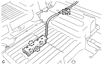
Disconnect the 3 connectors.
-
Remove the 2 nuts and battery smart unit.
-
-
REMOVE HV BATTERY
CAUTION:
Be sure to wear insulated gloves and protective goggles.
Note
-
Make sure to bundle the wire harness with insulation tape to prevent it from getting caught when removing components.
-
Insulate the removed terminals with insulating tape.
Tech Tips
Exchange the lower hybrid battery carrier panel as a set when liquids collect at the lower hybrid battery carrier panel and powder sticks.
-
Remove the HV battery module LH.
-
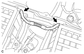
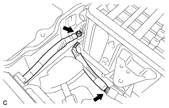
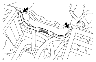
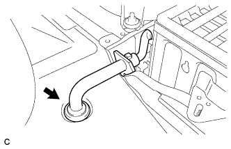
Remove the battery room ventilation hose between the HV battery module LH and center HV battery module.
-
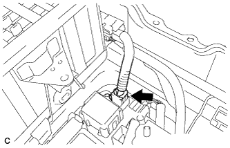
Disconnect the connector and clamp of the battery thermo sensor.
-
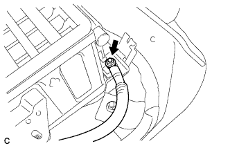
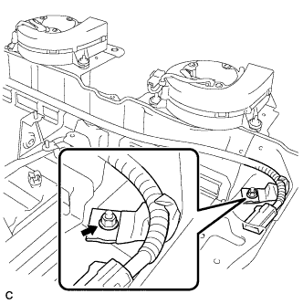
Remove the nut and main battery cable from the HV battery module LH.
Note
-
Insulate the tool with insulating tape.
-
Do not use a universal joint. Using a universal joint may cause the socket extension to drop and create a short circuit.
-
-
Disconnect the connector.
-
Remove the nut, then disconnect the EV battery plug from the HV battery module LH.
Note
-
Insulate the tool with insulating tape.
-
Do not use a universal joint. Using a universal joint may cause the socket extension to drop and create a short circuit.
-
-
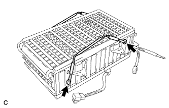
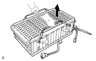
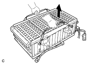
Remove the carry belts from the center HV battery module and install them to the HV battery module LH.
Note
Insert the ends of the carry belts into the installation holes. Pull the carry belts upward to securely install them.
-
Remove the HV battery module LH.
-
Remove the carry belts from the HV battery module LH.
-
-
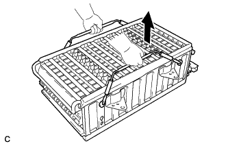
Remove the center HV battery module.
-
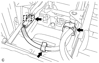
Disconnect the connector and clamp.
-
Separate the 2 wire harness clamps.
-
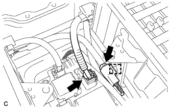
Disconnect the 2 connectors and clamp.
-
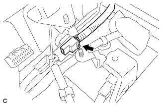
Disconnect the connector.
-
Disconnect the connector and clamp.
-
Remove the battery room ventilation hose between the center HV battery module and HV battery module RH.
-
Install the carry belts to the center HV battery module.
Note
Insert the ends of the carry belts into the installation holes. Pull the carry belts upward to securely install them.
-
Remove the center HV battery module.
-
Remove the carry belts from the center HV battery module.
-
-
Remove the HV battery module RH.
-
Disconnect the connector.
-
Remove the nut and the No. 2 HV battery pack cable.
Note
-
Insulate the tool with insulating tape.
-
Do not use a universal joint. Using a universal joint may cause the socket extension to drop and create a short circuit.
-
-
Remove the battery room ventilation hose.
-
Install the carry belts to the HV battery module RH.
Note
Insert the ends of the carry belts into the installation holes. Pull the carry belts upward to securely install them.
-
Remove the HV battery module RH.
-
Remove the carry belts from the HV battery module RH.
-
-
-
REMOVE NO. 2 HV BATTERY PACK CABLE
Tech Tips
Exchange the lower hybrid battery carrier panel as a set when liquids collect at the lower hybrid battery carrier panel and powder sticks.
-
Remove the nut and the No. 2 HV battery pack cable.
-
-
REMOVE BATTERY COOLING BLOWER ASSEMBLY
Tech Tips
Exchange the lower hybrid battery carrier panel as a set when liquids collect at the lower hybrid battery carrier panel and powder sticks.
-
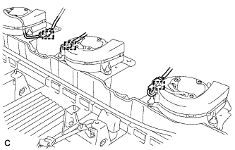
Disconnect each battery cooling blower assembly connector and 3 clamps.
-
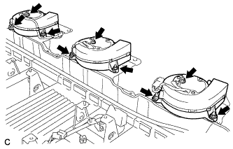
Remove the 9 nuts and 3 battery cooling blower assemblies.
-
-
REMOVE ELECTRIC VEHICLE BATTERY PLUG ASSEMBLY
Tech Tips
Exchange the lower hybrid battery carrier panel as a set when liquids collect at the lower hybrid battery carrier panel and powder sticks.
-
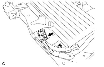
Disconnect the connector and clamp.
-
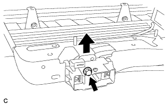
Remove the bolt and EV battery plug.
-
-
REMOVE HYBRID BATTERY JUNCTION BLOCK ASSEMBLY
Tech Tips
Exchange the lower hybrid battery carrier panel as a set when liquids collect at the lower hybrid battery carrier panel and powder sticks.
-
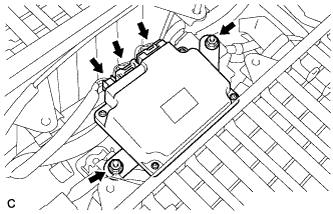
Remove the 2 nuts, then disconnect the No. 3 wire frame from the hybrid battery junction block assembly.
-
Disconnect the 2 main battery cable connectors from the hybrid battery junction block assembly.
-
Remove the 3 nuts and hybrid battery junction block assembly.
-
-
REMOVE HYBRID BATTERY CARRIER PANEL
Tech Tips
Exchange the lower hybrid battery carrier panel as a set when liquids collect at the lower hybrid battery carrier panel and powder sticks.
-
Remove the hybrid battery carrier panel from the vehicle.
-
-
REMOVE NO. 2 BATTERY PACKING
Tech Tips
Exchange the lower hybrid battery carrier panel as a set when liquids collect at the lower hybrid battery carrier panel and powder sticks.
-
Remove the No. 2 battery packing from the lower hybrid battery carrier panel.
-
-
REMOVE HYBRID BATTERY PACK WIRE
-
Disconnect the 3 clamps, then remove the battery pack wire from the lower hybrid battery carrier panel.
-
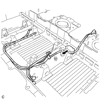
Remove the battery pack wire from the lower hybrid battery carrier panel.
Tech Tips
Remove the foam pad by pushing it in the direction shown in the illustration.
-
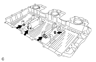
Remove the 4 clamps from hybrid battery carrier panel.
-