HYBRID BATTERY SYSTEM, Diagnostic DTC:P0A7F-123

| DTC Code | DTC Name |
|---|---|
| P0A7F-123 | Hybrid Battery Pack Deterioration |
DESCRIPTION
-
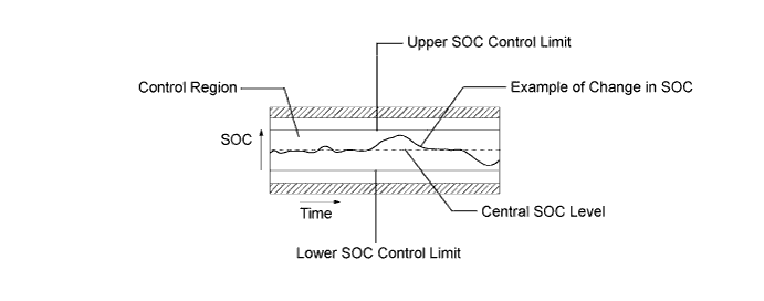
The battery smart unit and the power management control ECU calculate the SOC (state of charge) of the HV battery through the accumulated amperage in the HV battery. The battery smart unit sends the condition of the HV battery to the power management control ECU. Then the power management control ECU calculates the SOC based on the information and controls HV battery charge and discharge according to the driving condition.
DTC No. DTC Detection Condition Trouble Area P0A7F-123
-
Internal resistance of the HV battery is higher than the standard (1 trip detection)
-
Difference in the capacity between battery blocks is larger than the standard (2 trip detection)
-
HV battery assembly
-
Battery smart unit
Tech Tips
P0A7F-123 will not be set unless the vehicle is driven for approximately 10 minutes after clearing the DTC. (As 2 trip detection logic is used, check for DTCs including pending DTCs.)
-
INSPECTION PROCEDURE
CAUTION:
When disposing of an HV battery, make sure to return it through an authorized collection agent who is capable of handling it safely. If the HV battery is returned via the manufacturer specified route, it will be returned properly and in a safe manner by an authorized collection agent.
PROCEDURE
-
CHECK DTC OUTPUT (DTC P0AFC-123 IS OUTPUT)
-
Connect the intelligent tester to the DLC3.
-
Turn the power switch on (IG).
-
Enter the following menus: Powertrain / Hybrid Control / Trouble Codes.
-
Read output DTCs Click here.
Result Result Proceed to P0AFC-123 is not output. A P0AFC-123 is also output. B -
Disconnect the intelligent tester from the DLC3.
B 
GO TO DTC CHART
A 
-
-
READ VALUE USING INTELLIGENT TESTER (VB1 - VB15)
-
Ensure the safety of the areas in front and at the back of the vehicle.
-
Apply the parking brake and secure the wheels using chocks.
-
Connect the intelligent tester to the DLC3.
-
Turn the power switch on (READY).
-
Fully warm up the engine and turn the air conditioning off.
-
Enter the following menus: Powertrain / Hybrid Control / Data List / Battery Block Vol -V01 to V15.
-
Firmly depress the brake pedal with your left foot.
-
Move the shift lever to D.
-
Record each battery block voltage from the data list (Battery Block Vol - V01 to V15) while fully depressing the accelerator pedal.
-
Compare the battery block voltages (Battery Block Vol - V01 to V15) between the even and odd number groups in each combination shown in the table below.
Table 1 Circuit A Battery Block Circuit B Battery Block Condition Battery Block Vol-V01 (VB1) Battery Block Vol-V02 (VB2) "Battery Block Vol - V01" - "Battery Block Vol - V02" = 0.3 V or more Battery Block Vol-V04 (VB4) Battery Block Vol-V03 (VB3) "Battery Block Vol - V04" - "Battery Block Vol - V03" = 0.3 V or more Battery Block Vol-V05 (VB5) Battery Block Vol-V06 (VB6) "Battery Block Vol - V05" - "Battery Block Vol - V06" = 0.3 V or more Battery Block Vol-V08 (VB8) Battery Block Vol-V07 (VB7) "Battery Block Vol - V08" - "Battery Block Vol - V07" = 0.3 V or more Battery Block Vol-V09 (VB9) Battery Block Vol-V10 (VB10) "Battery Block Vol - V09" - "Battery Block Vol - V10" = 0.3 V or more Battery Block Vol-V12 (VB12) Battery Block Vol-V11 (VB11) "Battery Block Vol - V12" - "Battery Block Vol - V11" = 0.3 V or more Battery Block Vol-V13 (VB13) Battery Block Vol-V14 (VB14) "Battery Block Vol - V13" - "Battery Block Vol - V14" = 0.3 V or more Battery Block Vol-V12 (VB12) Battery Block Vol-V15 (VB15) "Battery Block Vol - V12" - "Battery Block Vol - V15" = 0.3 V or more Table 2 Circuit A Battery Block Circuit B Battery Block Condition Battery Block Vol-V01 (VB1) Battery Block Vol-V02 (VB2) "Battery Block Vol - V02" - "Battery Block Vol - V01" = 0.3 V or more Battery Block Vol-V04 (VB4) Battery Block Vol-V03 (VB3) "Battery Block Vol - V03" - "Battery Block Vol - V04" = 0.3 V or more Battery Block Vol-V05 (VB5) Battery Block Vol-V06 (VB6) "Battery Block Vol - V06" - "Battery Block Vol - V05" = 0.3 V or more Battery Block Vol-V08 (VB8) Battery Block Vol-V07 (VB7) "Battery Block Vol - V07" - "Battery Block Vol - V08" = 0.3 V or more Battery Block Vol-V09 (VB9) Battery Block Vol-V10 (VB10) "Battery Block Vol - V10" - "Battery Block Vol - V09" = 0.3 V or more Battery Block Vol-V12 (VB12) Battery Block Vol-V11 (VB11) "Battery Block Vol - V11" - "Battery Block Vol - V12" = 0.3 V or more Battery Block Vol-V13 (VB13) Battery Block Vol-V14 (VB14) "Battery Block Vol - V14" - "Battery Block Vol - V13" = 0.3 V or more Battery Block Vol-V12 (VB12) Battery Block Vol-V15 (VB15) "Battery Block Vol - V15" - "Battery Block Vol - V12" = 0.3 V or more Tech Tips
Make sure to compare Battery Block Vol-V15 to Battery Block Vol-V12 in accordance with the table above.
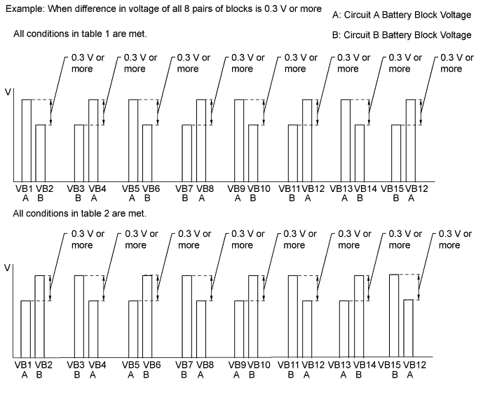
Tech Tips
When an internal malfunction occurs in the battery smart unit, this symptom (difference in voltage of 0.3 V or more for all 8 pairs of blocks) will occur.
Result Result Proceed to All conditions in table 1 are met. A All conditions in table 2 are met. Other than above. B -
Turn the power switch off.
-
Disconnect the intelligent tester from the DLC3.
B
REPLACE HV BATTERY ASSEMBLY Click here
A 
REPLACE BATTERY SMART UNIT Click here
-