CAMSHAFT POSITION SENSOR REMOVAL

-
PRECAUTION (w/ Air Suspension)
Note
Be sure to read Precaution thoroughly before servicing Click here.
-
REMOVE WINDSHIELD WIPER MOTOR AND LINK ASSEMBLY
-
Remove the windshield wiper motor and link assembly Click here.
-
-
REMOVE FRONT SHOCK ABSORBER CAP (w/ Air Suspension)
-
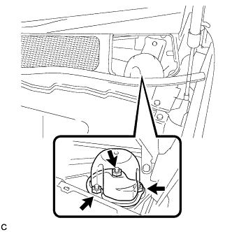
Remove the 3 nuts and front shock absorber cap.
-
-
REMOVE OUTER COWL TOP PANEL SUB-ASSEMBLY (for LHD)
-
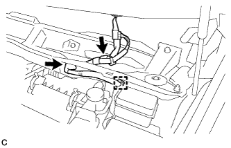
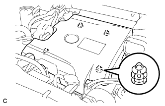
Disconnect the connector (w/ Windshield Deicer).
-
Disengage the grommet and clamp, and separate the wire harness.
-
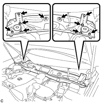
Remove the 6 nuts, 4 bolts and outer cowl top panel sub-assembly.
-
-
REMOVE OUTER COWL TOP PANEL SUB-ASSEMBLY (for RHD)
-
Disconnect the connector (w/ Windshield Deicer).
-
Disengage the grommet and clamp, and separate the wire harness.
-
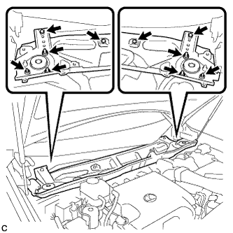
Remove the 6 nuts, 4 bolts and outer cowl top panel sub-assembly.
-
-
REMOVE V-BANK COVER SUB-ASSEMBLY
-
Hold the front of the V-bank cover sub-assembly and raise it to disengage the 2 retainers on the front of the V-bank cover sub-assembly. Continue to raise the V-bank cover sub-assembly to disengage the 2 retainers on the rear of the V-bank cover sub-assembly and remove the V-bank cover sub-assembly.
Note
Attempting to disengage both front and rear retainers at the same time may cause the V-bank cover sub-assembly to break.
-
-
REMOVE NO. 1 ENGINE UNDER COVER
-
DRAIN ENGINE COOLANT (for Engine)
Note
Do not remove the radiator cap, cylinder block drain cock plugs and radiator drain cock plug while the engine and radiator are still hot. Pressurized hot engine coolant and steam may be released and cause serious burns.
-
Loosen the radiator drain cock plug and drain the coolant.
Tech Tips
Collect the coolant in a container and dispose of it according to the regulations in your area.
-
Remove the radiator cap from the radiator assembly.
-
Loosen the 2 cylinder block drain cock plugs.
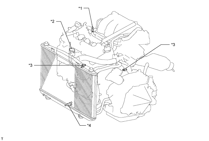
Text in Illustration *1 Air Drain Cock Plug *2 Radiator Cap *3 Cylinder Block Drain Cock Plug *4 Radiator Drain Cock Plug
-
-
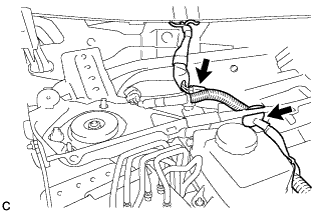
REMOVE INTAKE AIR RESONATOR SUB-ASSEMBLY
-
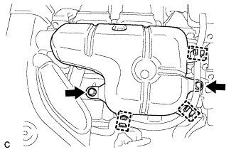
Remove the 3 clamps and Disconnect the water hose from the intake air resonator sub-assembly.
-
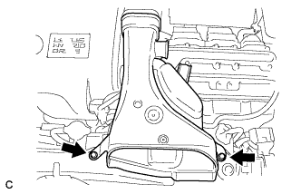
Remove the 2 bolts and intake air resonator sub-assembly from the inverter with converter assembly.
-
-
REMOVE NO. 2 AIR CLEANER INLET
-
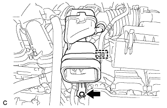
Remove the 2 bolts and inlet No. 2 air cleaner.
-
-
REMOVE NO. 1 AIR CLEANER INLET
-
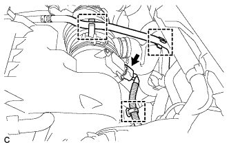
Disconnect the No. 1 fuel vapor feed hose from the inlet No. 1 air cleaner.
-
Remove the bolt and inlet No. 1 air cleaner.
-
-
REMOVE AIR CLEANER ASSEMBLY
-
Disconnect the mass air flow meter connector and wire harness clamp.
-
Separate the fuel vapor feed hose from the 2 hose clamps.
-
Disconnect the ventilation hose.
-
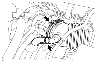
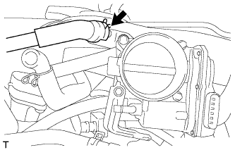
Loosen the hose clamp and separate the air cleaner hose from the throttle body.
-
Remove the 2 bolts and remove the air cleaner assembly with hose.
-
-
REMOVE INTAKE AIR SURGE TANK ASSEMBLY
-
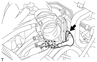
Disconnect the throttle body assembly connector and wire harness clamp.
-
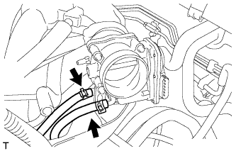
Disconnect the fuel vapor feed hose.
-
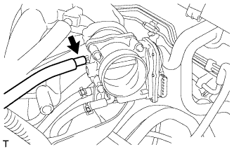
Disconnect the 2 water by-pass hoses.
-
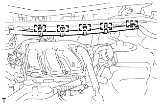
Disconnect the 5 clamps and separate the main wire.
-
Disconnect the ventilation hose.
-
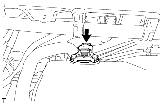
Disconnect the connector from the manifold absolute pressure sensor.
-
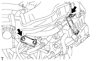
Remove the bolt and separate the No. 1 surge tank stay from the intake air surge tank assembly.
-
Remove the bolt and separate the throttle body bracket from the intake air surge tank assembly.
-
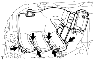
Remove the 2 nuts from the intake air surge tank assembly.
-
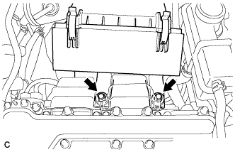
Using a 5 mm socket hexagon wrench, remove the 4 bolts.
-
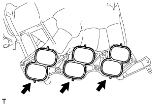
Remove the intake air surge tank assembly and 3 air surge tank to intake manifold gaskets.
-
-
REMOVE NO. 2 EGR PIPE
-
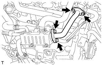
Remove the 2 nuts, 2 bolts, No. 2 EGR pipe and 2 gaskets.
-
-
REMOVE EGR DELIVERY CHAMBER
-
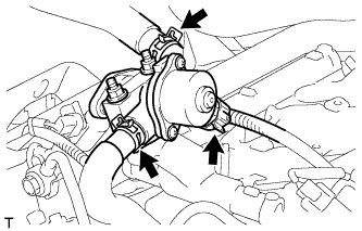
Disconnect the 2 water hoses and connector (w/ EGR System).
-
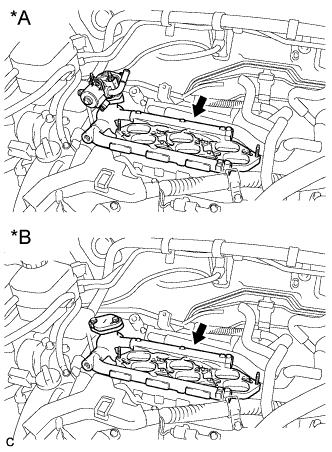
Text in Illustration *A w/ EGR System *B w/o EGR System Remove the EGR delivery chamber.
-
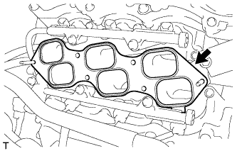
Remove the No. 2 intake manifold gasket.
-
-
REMOVE VVT SENSOR (for Bank 2)
-
Disconnect the sensor connector.
-
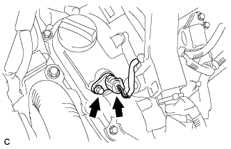
Remove the bolt and sensor.
-
-
REMOVE VVT SENSOR (for Bank 1)
-
Disconnect the sensor connector.
-
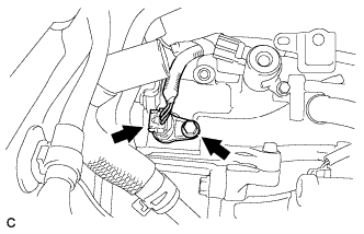
Remove the bolt and sensor.
-