DESCRIPTION
When the power switch is turned on (IG), the battery voltage is applied to IGSW of the ECM. The output signal from the MREL terminal of the ECM causes a current to flow to the coil, closing the contact of the EFI MAIN relay and supplying power to terminals +B and +B2 of the ECM.
INSPECTION PROCEDURE
Inspect the fuses for circuits related to this system before performing the following inspection procedure.
PROCEDURE
- Click here
CHECK HARNESS AND CONNECTOR (ECM - BODY GROUND)
-

Disconnect the ECM connector.
-
Measure the resistance according to the value(s) in the table below.
Standard Resistance Tester Connection Condition Specified Condition D1-46 (E1) - Body ground Always Below 1 Ω Table 1. Text in Illustration *1 Front view of wire harness connector
(to ECM)
-
Reconnect the ECM connector.
- OKClick here
- NGClick here
-
- Click here
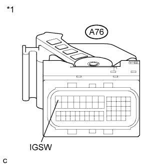
INSPECT ECM (IGSW VOLTAGE)
-
Disconnect the ECM connector.
-
Turn the power switch on (IG).
-
Measure the voltage according to the value(s) in the table below.
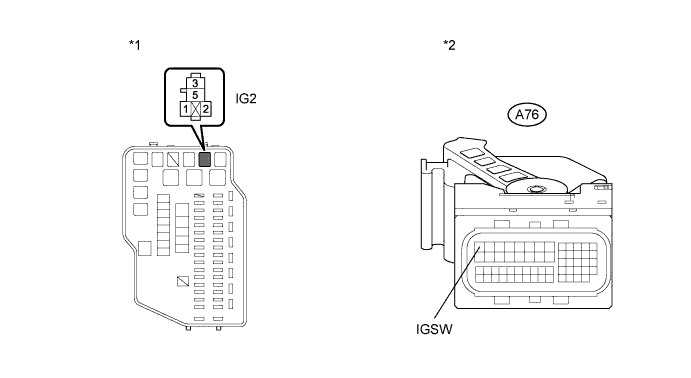
Standard Voltage Tester Connection Switch Condition Specified Condition A76-1 (IGSW) - Body ground Power switch on (IG) 11 to 14 V Table 2. Text in Illustration *1 Front view of wire harness connector
(to ECM)
-
Reconnect the ECM connector.
- OKClick here
- NGClick here
-
- Click here
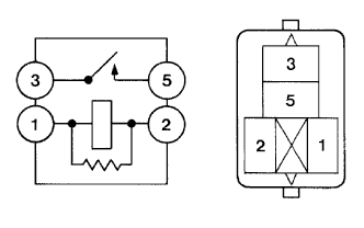
INSPECT RELAY (EFI MAIN RELAY)
-
Remove the EFI MAIN relay from the engine room relay block.
-
Measure the resistance according to the value(s) in the table below.
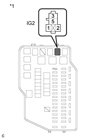
Standard Resistance Tester Connection Condition Specified Condition 3 - 5 No battery voltage applied to terminals 1 and 2 10 kΩ or higher Battery voltage applied to terminals 1 and 2 Below 1 Ω -
Reinstall the EFI MAIN relay.
- OKClick here
- NGClick here
-
- Click here
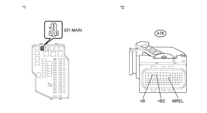
CHECK HARNESS AND CONNECTOR (EFI MAIN RELAY - ECM)
-
Remove the EFI MAIN relay from the engine room relay block.
-
Disconnect the ECM connector.
-
Measure the resistance according to the value(s) in the table below.
Standard Resistance (Check for Open) Tester Connection Condition Specified Condition 3 (EFI MAIN relay terminal) - A76-3 (+B) Always Below 1 Ω 3 (EFI MAIN relay terminal) - A76-4 (+B2) Always Below 1 Ω 1 (EFI MAIN relay terminal) - A76-21 (MREL) Always Below 1 Ω Standard Resistance (Check for Short) Tester Connection Condition Specified Condition 3 (EFI MAIN relay terminal) or A76-3 (+B) - Body ground Always 10 kΩ or higher 3 (EFI MAIN relay terminal) or A76-4 (+B2) - Body ground Always 10 kΩ or higher 1 (EFI MAIN relay terminal) or A76-21 (MREL) - Body ground Always 10 kΩ or higher Table 3. Text in Illustration *1 Engine Room Relay Block *2 Front view of wire harness connector
(to ECM)
-
Reconnect the ECM connector.
-
Reinstall the EFI MAIN relay.
- OKClick here
- NGClick here
-
- Click here
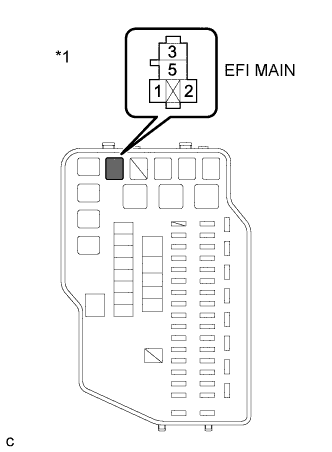
CHECK HARNESS AND CONNECTOR (BATTERY - EFI MAIN RELAY)
-
Remove the EFI MAIN relay from the engine room relay block.
-
Disconnect the cable from the negative (-) battery terminal.
-
Disconnect the cable from the positive (+) battery terminal.
-
Measure the resistance according to the value(s) in the table below.
Standard Resistance (Check for Open) Tester Connection Condition Specified Condition 5 (EFI MAIN relay terminal) - Battery positive (+) terminal Always Below 1 Ω Standard Resistance (Check for Short) Tester Connection Condition Specified Condition 5 (EFI MAIN relay terminal) - Body ground Always 10 kΩ or higher Table 4. Text in Illustration *1 Engine Room Relay Block -
Reinstall the EFI MAIN relay.
-
Reconnect the cable to the positive (+) battery terminal.
-
Reconnect the cable to the negative (-) battery terminal.
- OKClick here
- NGClick here
-
- Click here
CHECK HARNESS AND CONNECTOR (EFI MAIN RELAY - BODY GROUND)
-
Remove the EFI MAIN relay from the engine room relay block.
-
Measure the resistance according to the value(s) in the table below.
Standard Resistance (Check for Open) Tester Connection Condition Specified Condition 2 (EFI MAIN relay terminal) - Body ground Always Below 1 Ω Table 5. Text in Illustration *1 Engine Room Relay Block -
Reinstall the EFI MAIN relay.
- OKClick here
- NGClick here
-
- Click here
INSPECT RELAY (IG2 RELAY)
-

Remove the IG2 relay from the engine room relay block.
-
Measure the resistance according to the value(s) in the table below.
Standard Resistance Tester Connection Condition Specified Condition 3 - 5 No battery voltage applied to terminals 1 and 2 10 kΩ or higher 3 - 5 Battery voltage applied to terminals 1 and 2 Below 1 Ω -
Reinstall the IG2 relay.
- OKClick here
- NGClick here
-
- Click here
CHECK HARNESS AND CONNECTOR (IG2 RELAY - ECM)
-
Remove the IG2 relay from the engine room relay block.
-
Disconnect the ECM connector.
-
Measure the resistance according to the value(s) in the table below.
Standard Resistance (Check for Open) Tester Connection Condition Specified Condition 3 (IG2 relay terminal) - A76-1 (IGSW) Always Below 1 Ω Standard Resistance (Check for Short) Tester Connection Condition Specified Condition 3 (IG2 relay terminal) or A76-1 (IGSW) - Body ground Always 10 kΩ or higher Table 6. Text in Illustration *1 Engine Room Relay Block *2 Front view of wire harness connector
(to ECM)
-
Reinstall the IG2 relay.
-
Reconnect the ECM connector.
- OKClick here
- NGClick here
-
- Click here
CHECK HARNESS AND CONNECTOR (IG2 RELAY POWER SOURCE)
-
Remove the IG2 relay from the engine room relay block.
-
Measure the voltage according to the value(s) in the table below.
Standard Voltage Tester Connection Condition Specified Condition 5 (IG2 relay terminal) - Body ground Always 11 to 14 V Table 7. Text in Illustration *1 Engine Room Relay Block -
Reinstall the IG2 relay.
- OKClick here
- NGClick here
-
- Click here
CHECK HARNESS AND CONNECTOR (IG2 RELAY - BODY GROUND)
-
Remove the IG2 relay from the engine room relay block.
-
Measure the resistance according to the value(s) in the table below.
Standard Resistance (Check for Open) Tester Connection Condition Specified Condition 2 (IG2 relay terminal) - Body ground Always Below 1 Ω Table 8. Text in Illustration *1 Engine Room Relay Block -
Reinstall the IG2 relay.
- OKClick here
- NGClick here
-
- Click here
CHECK HARNESS AND CONNECTOR (IG2 RELAY - POWER MANAGEMENT CONTROL ECU)
-
Disconnect the power management control ECU connector.
-
Remove the IG2 relay from the engine room relay block.
-
Measure the resistance according to the value(s) in the table below.
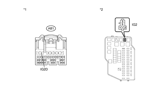
Standard Resistance (Check for Open) Tester Connection Condition Specified Condition 1 (IG2 relay terminal) - A81-2 (IG2D) Always Below 1 Ω Standard Resistance (Check for Short) Tester Connection Condition Specified Condition 1 (IG2 relay terminal) or A81-2 (IG2D) - Body ground Always 10 kΩ or higher Table 9. Text in Illustration *1 Front view of wire harness connector
(to Power Management Control ECU)
*2 Engine Room Relay Block -
Reconnect the power management control ECU connector.
-
Reinstall the IG2 relay.
- OKClick here
- NGClick here
-
- Click here
REPAIR OR REPLACE HARNESS OR CONNECTOR (ECM - BODY GROUND)
- Click here
REPLACE RELAY (EFI MAIN RELAY)
- Click here
REPAIR OR REPLACE HARNESS OR CONNECTOR (EFI MAIN RELAY - ECM)
- Click here
REPAIR OR REPLACE HARNESS OR CONNECTOR (BATTERY - EFI MAIN RELAY)
- Click here
REPAIR OR REPLACE HARNESS OR CONNECTOR (EFI MAIN RELAY - BODY GROUND)
- Click here
PROCEED TO NEXT SUSPECTED AREA SHOWN IN PROBLEM SYMPTOMS TABLEClick here
- Click here
REPLACE RELAY (IG2 RELAY)
- Click here
REPAIR OR REPLACE HARNESS OR CONNECTOR (IG2 RELAY - ECM)
- Click here
REPAIR OR REPLACE HARNESS OR CONNECTOR (IG2 RELAY - BATTERY)
- Click here
REPAIR OR REPLACE HARNESS OR CONNECTOR (IG2 RELAY - BODY GROUND)
- Click here
REPAIR OR REPLACE HARNESS OR CONNECTOR (IG2 RELAY - POWER MANAGEMENT CONTROL ECU)
- Click here
GO TO ENTRY AND START SYSTEMClick here