REAR VIEW MONITOR SYSTEM (for Inner Rear View Mirror Type) TERMINALS OF ECU

-
REAR TELEVISION CAMERA ASSEMBLY
-
Disconnect the Y14 rear television camera assembly connector.

-
Measure the voltage of each terminal of the wire harness side connector.
Terminal No. (Symbol) Wiring Color Terminal Description Condition Specified Condition Y14-3 (CGND) - Body ground G - Body ground Ground Always Below 1 V Y14-4 (CB+) - Y14-3 (CGND) B - G Power source Power switch on (IG)
Shift lever in R
5.5 to 7.05 V If the result is not as specified, there may be a malfunction on the wire harness side.
-
Reconnect the Y14 rear television camera assembly connector.
-
Check for pulses between each terminal of the connector.
Terminal No. (Symbol) Wiring Color Terminal Description Condition Specified Condition Y14-2 (CV+) - Y14-1 (CV-) R - W Video signal Power switch on (IG)
Shift lever in R
Camera lens not covered, displaying an image
Pulse generation
(See waveform 1)
Power switch on (IG)
Shift lever in R
Camera lens covered, blacking out screen
Pulse generation
(See waveform 2)
Tech Tips
A waterproof connector is used for the rear television camera assembly. Therefore, inspect the waveform at the inner rear view mirror assembly with the connector connected.
If the result is not as specified, the rear television camera assembly may have a malfunction.
-
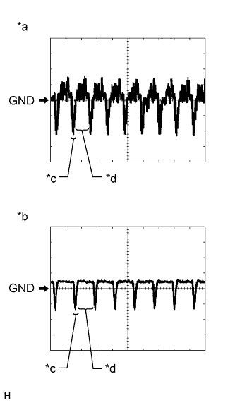
Text in Illustration *a Waveform 1 (camera lens not covered, displaying an image) *b Waveform 2 (camera lens is covered, blacking out the screen) *c Synchronization Signal *d Video Waveform Reference (Oscilloscope waveform):
Tech Tips
A waterproof connector is used for the television camera assembly. Therefore, inspect the waveform at the inner rear view mirror assembly with the connector connected.
-
Waveform 1 (camera lens is not covered, displaying an image)
Item Content Terminal No. (Symbol) Y14-2 (CV+) - Y14-1 (CV-) Tool Setting 200 mV/DIV., 50 μsec./DIV. Condition Power switch on (IG), shift lever in R Tech Tips
The video waveform changes according to the image sent by the television camera assembly.
-
Waveform 2 (camera lens is covered, blacking out the screen)
Item Content Terminal No. (Symbol) Y14-2 (CV+) - Y14-1 (CV-) Tool Setting 200 mV/DIV., 50 μsec./DIV. Condition Power switch on (IG), shift lever in R Tech Tips
The video waveform changes according to the image sent by the rear television camera assembly.
-
-
-
INNER REAR VIEW MIRROR ASSEMBLY
-
Disconnect the T5 rear view mirror assembly connector.

-
Measure the voltage of each terminal of the wire harness side connector.
Terminal No. (Symbol) Wiring Color Terminal Description Condition Specified Condition T5-1 (IG) - Body ground B - Body ground Power switch signal Power switch off Below 1 V Power switch on (IG) 11 to 14 V T5-2 (E) - Body ground W - Body ground Ground Always Below 1 V T5-3 (REV) - T5-2 (E) G - W Reverse signal Power switch on (IG)
Shift lever in any position except R
Below 1 V Power switch on (IG)
Shift lever in R
11 to 14 V T5-13 (CGND) - T5-2 (E) Shielded - W Rear television camera ground (shielded) Always Below 1 V T5-14 (CB+) - T5-2 (E) B - W Power source to television camera Power switch on (IG)
Shift lever in R
5.5 to 7.05 V T5-6 (CV-) - T5-2 (E) W - W Rear television camera ground Always Below 1 V If the result is not as specified, there may be a malfunction on the wire harness side.
-
Reconnect the T5 rear view mirror assembly connector.
-
Check for pulses between each terminal of the connector.
Terminal No. (Symbol) Wiring Color Terminal Description Condition Specified Condition T5-7 (CV+) - T5-2 (E) R - W Video signal Power switch on (IG)
Shift lever in R
Camera lens not covered, displaying an image
Pulse generation
(See waveform 1)
Power switch on (IG)
Shift lever in R
Camera lens covered, blacking out screen
Pulse generation
(See waveform 2)
Tech Tips
A waterproof connector is used for the rear television camera assembly. Therefore, inspect the waveform at the inner rear view mirror assembly with the connector connected.
If the result is not as specified, the rear television camera assembly may have a malfunction.
-
Text in Illustration *a Waveform 1 (camera lens not covered, displaying an image) *b Waveform 2 (camera lens is covered, blacking out the screen) *c Synchronization Signal *d Video Waveform Reference (Oscilloscope waveform):
Tech Tips
A waterproof connector is used for the rear television camera assembly. Therefore, inspect the waveform at the inner rear view mirror assembly with the connector connected.
-
Waveform 1 (camera lens is not covered, displaying an image)
Item Content Terminal No. (Symbol) T5-7 (CV+) - T5-2 (E) Tool Setting 200 mV/DIV., 50 μsec./DIV. Condition Power switch on (IG), shift lever in R Tech Tips
The video waveform changes according to the image sent by the rear television camera assembly.
-
Waveform 2 (camera lens is covered, blacking out the screen)
Item Content Terminal No. (Symbol) T5-7 (CV+) - T5-2 (E) Tool Setting 200 mV/DIV., 50 μsec./DIV. Condition Power switch on (IG), shift lever in R Tech Tips
The video waveform changes according to the image sent by the rear television camera assembly.
-
-