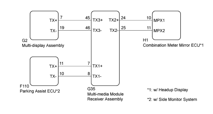
NAVIGATION SYSTEM AVC-LAN Circuit
DESCRIPTION
Each unit of the navigation system connected to the AVC-LAN (communication bus) transfers the switch signals using the AVC-LAN.
If a short to +B or short to ground occurs in the AVC-LAN, the navigation system will not function normally because communication is not possible.
WIRING DIAGRAM
INSPECTION PROCEDURE
Note
-
When replacing the multi-media module receiver assembly or telematics transceiver, perform vehicle contract setting (w/ Telematics Transceiver) Click here.
-
When replacing the multi-media module receiver assembly, perform vehicle contract setting (w/o Telematics Transceiver) Click here.
w/ G-BOOK System:
Tech Tips
The multi-media module receiver assembly is the master unit.
PROCEDURE
-
INSPECT MULTI-MEDIA MODULE RECEIVER ASSEMBLY
-
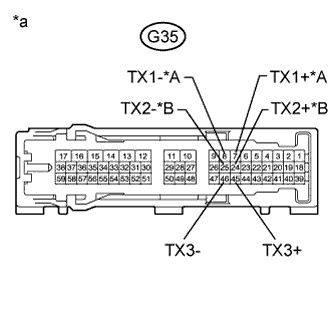
Text in Illustration *A w/ Side Monitor System *B w/ Headup Display *a Component without harness connected
(Multi-media Module Receiver Assembly)
Disconnect the G35 multi-media module receiver assembly connector.
-
Measure the resistance according to the value(s) in the table below.
Standard Resistance Tester Connection Condition Specified Condition G35-7 (TX1+) - G35-8 (TX1-)*1 Always 60 to 80 Ω G35-24 (TX2+) - G35-25 (TX2-)*2 Always 60 to 80 Ω G35-45 (TX3+) - G35-46 (TX3-) Always 60 to 80 Ω
-
*1: w/ Side Monitor System
-
*2: w/ Headup Display
-
NG 
REPLACE MULTI-MEDIA MODULE RECEIVER ASSEMBLY Click here
OK 
-
-
CHECK HARNESS AND CONNECTOR (MULTI-MEDIA MODULE RECEIVER ASSEMBLY - MULTI-DISPLAY ASSEMBLY)
-
Disconnect the G35 multi-media module receiver assembly connector.
-
Disconnect the G2 multi-display assembly connector.
-
Measure the resistance according to the value(s) in the table below.
Standard Resistance Tester Connection Condition Specified Condition G35-45 (TX3+) - G2-7 (TX+) Always Below 1 Ω G35-46 (TX3-) - G2-19 (TX-) Always Below 1 Ω G35-45 (TX3+) - Body ground Always 10 kΩ or higher G35-46 (TX3-) - Body ground Always 10 kΩ or higher -
Proceed to the next step based on the inspection result.
Result Condition Proceed to OK (w/ Headup display) A OK (w/o Headup display and w/ Side Monitor System) B OK (w/o Headup display and w/o Side Monitor System) C NG D
B 
CHECK HARNESS AND CONNECTOR (MULTI-MEDIA MODULE RECEIVER ASSEMBLY - PARKING ASSIST ECU) Click here
C
INSPECT MALFUNCTIONING PARTS Click here
D
REPAIR OR REPLACE HARNESS OR CONNECTOR
A
-
-
CHECK HARNESS AND CONNECTOR (MULTI-MEDIA MODULE RECEIVER ASSEMBLY - COMBINATION METER MIRROR ECU)
-
Disconnect the G35 multi-media module receiver assembly connector.
-
Disconnect the H1 combination meter mirror ECU connector.
-
Measure the resistance according to the value(s) in the table below.
Standard Resistance Tester Connection Condition Specified Condition G35-24 (TX2+) - H1-10 (MPX1) Always Below 1 Ω G35-25 (TX2-) - H1-11 (MPX2) Always Below 1 Ω G35-24 (TX2+) - Body ground Always 10 kΩ or higher G35-25 (TX2-) - Body ground Always 10 kΩ or higher -
Proceed to the next step based on the inspection result.
Result Condition Proceed to OK (w/ Side Monitor System) A OK (w/o Side Monitor System) B NG C
B
INSPECT MALFUNCTIONING PARTS Click here
C
REPAIR OR REPLACE HARNESS OR CONNECTOR
A
-
-
CHECK HARNESS AND CONNECTOR (MULTI-MEDIA MODULE RECEIVER ASSEMBLY - PARKING ASSIST ECU)
-
Disconnect the G35 multi-media module receiver assembly connector.
-
Disconnect the F110 parking assist ECU connector.
-
Measure the resistance according to the value(s) in the table below.
Standard Resistance Tester Connection Condition Specified Condition G35-7 (TX1+) - F110-11 (TX+) Always Below 1 Ω G35-8 (TX1-) - F110-10 (TX-) Always Below 1 Ω G35-7 (TX1+) - Body ground Always 10 kΩ or higher G35-8 (TX1-) - Body ground Always 10 kΩ or higher
NG
REPAIR OR REPLACE HARNESS OR CONNECTOR
OK
-
-
INSPECT MALFUNCTIONING PARTS
-
Disconnect and reconnect each slave unit one by one until the master unit returns to normal operation.
Tech Tips
-
Check all slave units.
-
If disconnecting a slave unit causes the master unit to return to normal operation, the slave unit is defective and should be replaced.
OK Master unit returns to normal operation. -
NG
REPLACE MULTI-MEDIA MODULE RECEIVER ASSEMBLY Click here
OK 
REPLACE MALFUNCTIONING PARTS
-