NAVIGATION SYSTEM Speaker Circuit
DESCRIPTION
If there is a short in a speaker circuit, the stereo component amplifier assembly detects the short and stops output to the speakers.
Thus sound cannot be heard from the speakers even if there is no malfunction in the stereo component amplifier assembly or speakers.
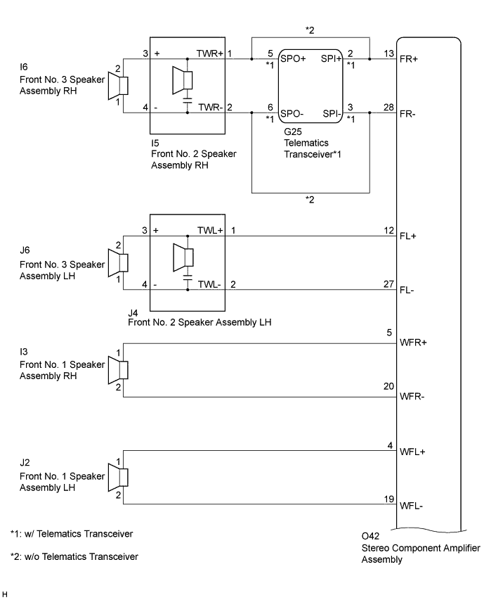
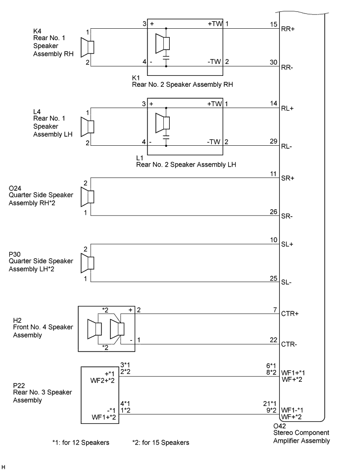
WIRING DIAGRAM
INSPECTION PROCEDURE
Note
When replacing the multi-media module receiver assembly or telematics transceiver, perform vehicle contract setting (w/ Telematics Transceiver) Click here.
PROCEDURE
-
CHECK HARNESS AND CONNECTOR
-
Disconnect the O42 stereo component amplifier assembly connector.
-
Disconnect the G25 telematics transceiver connector (w/ Telematics Transceiver).
-
Disconnect the I6 and J6 front No. 3 speaker assembly connectors.
-
Disconnect the I5 and J4 front No. 2 speaker assembly connectors.
-
Disconnect the I3 and J2 front No. 1 speaker assembly connectors.
-
Disconnect the K4 and L4 rear No. 1 speaker assembly connectors.
-
Disconnect the K1 and L1 rear No. 2 speaker assembly connectors.
-
Disconnect the O24 and P30 quarter side speaker assembly connectors (for 15 Speakers).
-
Disconnect the H2 front No. 4 speaker assembly connector.
-
Disconnect the P22 rear No. 3 speaker assembly connector.
-
Measure the resistance between the stereo component amplifier assembly and the telematics transceiver to check for an open circuit in the wire harness (w/ Telematics Transceiver).
Standard Resistance Tester Connection Condition Specified Condition O42-13 (FR+) - G25-2 (SPI+) Always Below 1 Ω O42-28 (FR-) - G25-3 (SPI-) Always Below 1 Ω -
Measure the resistance between the front No. 2 speaker assembly RH and the telematics transceiver to check for an open circuit in the wire harness (w/ Telematics Transceiver).
Standard Resistance Tester Connection Condition Specified Condition G25-5 (SPO+) - I5-1 (TWR+) Always Below 1 Ω G25-6 (SPO-) - I5-2 (TWR-) Always Below 1 Ω -
Measure the resistance between the front No. 2 speaker assembly RH and the stereo component amplifier assembly to check for an open circuit in the wire harness (w/o Telematics Transceiver).
Standard Resistance Tester Connection Condition Specified Condition O42-13 (FR+) - I5-1 (TWR+) Always Below 1 Ω O42-28 (FR-) - I5-2 (TWR-) Always Below 1 Ω -
Measure the resistance between the front No. 2 speaker assembly LH and the stereo component amplifier assembly to check for an open circuit in the wire harness.
Standard Resistance Tester Connection Condition Specified Condition O42-12 (FL+) - J4-1 (TWL+) Always Below 1 Ω O42-27 (FL-) - J4-2 (TWL-) Always Below 1 Ω -
Measure the resistance between each of the front No. 2 speaker assemblies and the front No. 3 speaker assemblies to check for an open circuit in the wire harness.
Standard Resistance Tester Connection Condition Specified Condition I5-3 (+) - I6-2 Always Below 1 Ω I5-4 (-) - I6-1 Always Below 1 Ω J4-3 (+) - J6-2 Always Below 1 Ω J4-4 (-) - J6-1 Always Below 1 Ω -
Measure the resistance between each of the front No. 1 speaker assemblies and the stereo component amplifier assembly to check for an open circuit in the wire harness.
Standard Resistance Tester Connection Condition Specified Condition O42-5 (WFR+) - I3-1 Always Below 1 Ω O42-20 (WFR-) - I3-2 Always Below 1 Ω O42-4 (WFL+) - J2-1 Always Below 1 Ω O42-19 (WFL-) - J2-2 Always Below 1 Ω -
Measure the resistance between each of the rear No. 2 speaker assemblies and the stereo component amplifier assembly to check for an open circuit in the wire harness.
Standard Resistance Tester Connection Condition Specified Condition O42-15 (RR+) - K1-1 (+TW) Always Below 1 Ω O42-30 (RR-) - K1-2 (-TW) Always Below 1 Ω O42-14 (RL+) - L1-1 (+TW) Always Below 1 Ω O42-29 (RL-) - L1-2 (-TW) Always Below 1 Ω -
Measure the resistance between each of the rear No. 1 speaker assemblies and the rear No. 2 speaker assemblies to check for an open circuit in the wire harness.
Standard Resistance Tester Connection Condition Specified Condition K4-1 - K1-3 (+) Always Below 1 Ω K4-2 - K1-4 (-) Always Below 1 Ω L4-1 - L1-3 (+) Always Below 1 Ω L4-2 - L1-4 (-) Always Below 1 Ω -
Measure the resistance between each of the quarter side speaker assemblies and the stereo component amplifier assembly to check for an open circuit in the wire harness (for 15 Speakers).
Standard Resistance Tester Connection Condition Specified Condition O42-11 (SR+) - O24-2 Always Below 1 Ω O42-26 (SR-) - O24-1 Always Below 1 Ω O42-10 (SL+) - P30-2 Always Below 1 Ω O42-25 (SL-) - P30-1 Always Below 1 Ω -
Measure the resistance between the front No. 4 speaker assembly and the stereo component amplifier assembly to check for an open circuit in the wire harness.
Standard Resistance Tester Connection Condition Specified Condition O42-7 (CTR+) - H2-2 (+) Always Below 1 Ω O42-22 (CTR-) - H2-1 (-) Always Below 1 Ω -
Measure the resistance between the rear No. 3 speaker assembly and the stereo component amplifier assembly to check for an open circuit in the wire harness.
Standard Resistance for 12 Speakers Tester Connection Condition Specified Condition O42-6 (WF1+) - P22-3 (+) Always Below 1 Ω O42-21 (WF1-) - P22-4 (-) Always Below 1 Ω for 15 Speakers Tester Connection Condition Specified Condition O42-8 (WF+) - P22-2 (WF2+) Always Below 1 Ω O42-9 (WF+) - P22-1 (WF1+) Always Below 1 Ω -
Measure the resistance between the stereo component amplifier assembly and body ground to check for a short circuit in the wire harness.
Standard Resistance Tester Connection Condition Specified Condition O42-13 (FR+) - Body ground Always 10 kΩ or higher O42-28 (FR-) - Body ground Always 10 kΩ or higher O42-12 (FL+) - Body ground Always 10 kΩ or higher O42-27 (FL-) - Body ground Always 10 kΩ or higher O42-5 (WFR+) - Body ground Always 10 kΩ or higher O42-20 (WFR-) - Body ground Always 10 kΩ or higher O42-4 (WFL+) - Body ground Always 10 kΩ or higher O42-19 (WFL-) - Body ground Always 10 kΩ or higher O42-15 (RR+) - Body ground Always 10 kΩ or higher O42-30 (RR-) - Body ground Always 10 kΩ or higher O42-14 (RL+) - Body ground Always 10 kΩ or higher O42-29 (RL-) - Body ground Always 10 kΩ or higher O42-11 (SR+) - Body ground*1 Always 10 kΩ or higher O42-26 (SR-) - Body ground*1 Always 10 kΩ or higher O42-10 (SL+) - Body ground*1 Always 10 kΩ or higher O42-25 (SL-) - Body ground*1 Always 10 kΩ or higher O42-7 (CTR+) - Body ground Always 10 kΩ or higher O42-22 (CTR-) - Body ground Always 10 kΩ or higher O42-8 (WF+) - Body ground*1 Always 10 kΩ or higher O42-9 (WF+) - Body ground*1 Always 10 kΩ or higher O42-6 (WF1+) - Body ground*2 Always 10 kΩ or higher O42-21 (WF1-) - Body ground*2 Always 10 kΩ or higher
-
*1: for 15 Speakers
-
*2: for 12 Speakers
-
-
Measure the resistance between the telematics transceiver and body ground to check for a short circuit in the wire harness (w/ Telematics Transceiver).
Standard Resistance Tester Connection Condition Specified Condition G25-5 (SPO+) - Body ground Always 10 kΩ or higher G25-6 (SPO-) - Body ground Always 10 kΩ or higher -
Measure the resistance between each of the front No. 2 speaker assemblies and body ground to check for a short circuit in the wire harness.
Standard Resistance Tester Connection Condition Specified Condition I5-3 (+) - Body ground Always 10 kΩ or higher I5-4 (-) - Body ground Always 10 kΩ or higher J4-3 (+) - Body ground Always 10 kΩ or higher J4-4 (-) - Body ground Always 10 kΩ or higher -
Measure the resistance between each of the rear No. 2 speaker assemblies and body ground to check for a short circuit in the wire harness.
Standard Resistance Tester Connection Condition Specified Condition K1-3 (+) - Body ground Always 10 kΩ or higher K1-4 (-) - Body ground Always 10 kΩ or higher L1-3 (+) - Body ground Always 10 kΩ or higher L1-4 (-) - Body ground Always 10 kΩ or higher
NG 
REPAIR OR REPLACE HARNESS OR CONNECTOR
OK 
-
-
INSPECT FRONT NO. 1 SPEAKER ASSEMBLY
-
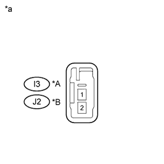
Text in Illustration *A for RH *B for LH *a Component without harness connected
(Front No. 1 Speaker Assembly)
Resistance check
-
Measure the resistance according to the value(s) in the table below.
Standard Resistance for 12 Speakers Tester Connection Condition Specified Condition I3-1 - I3-2 Always 3.2 to 4.8 Ω J2-1 - J2-2 Always 3.2 to 4.8 Ω for 15 Speakers Tester Connection Condition Specified Condition I3-1 - I3-2 Always 5.0 to 7.0 Ω J2-1 - J2-2 Always 5.0 to 7.0 Ω
-
NG
REPLACE FRONT NO. 1 SPEAKER ASSEMBLY Click here
OK
-
-
INSPECT FRONT NO. 2 SPEAKER ASSEMBLY
-
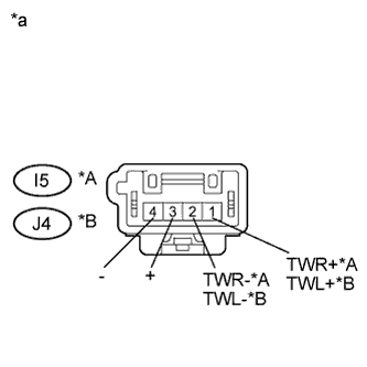
Text in Illustration *A for RH *B for LH *a Component without harness connected
(Front No. 2 Speaker Assembly)
Resistance check
-
Measure the resistance according to the value(s) in the table below.
Standard Resistance Tester Connection Condition Specified Condition I5-1 (TWR+) - I5-2 (TWR-) Always 10 kΩ or higher I5-1 (TWR+) - I5-3 (+) Always Below 1 Ω I5-2 (TWR-) - I5-4 (-) Always Below 1 Ω J4-1 (TWL+) - J4-2 (TWL-) Always 10 kΩ or higher J4-1 (TWL+) - J4-3 (+) Always Below 1 Ω J4-2 (TWL-) - J4-4 (-) Always Below 1 Ω
-
NG
REPLACE FRONT NO. 2 SPEAKER ASSEMBLY Click here
OK
-
-
REPLACE FRONT NO. 2 SPEAKER ASSEMBLY
-
Check that the malfunction disappears when a known good speaker is installed Click here.
OK Malfunction disappears. Tech Tips
-
Connect all the connectors to the front No. 2 speaker assemblies that were disconnected.
-
When there is a possibility that either the right or left front speaker is defective, inspect by interchanging the right one with the left one.
-
Perform the above inspection on both LH and RH sides.
-
NG 
INSPECT FRONT NO. 3 SPEAKER ASSEMBLY Click here
OK 
END (FRONT NO. 2 SPEAKER ASSEMBLY WAS DEFECTIVE)
-
-
INSPECT FRONT NO. 3 SPEAKER ASSEMBLY
-
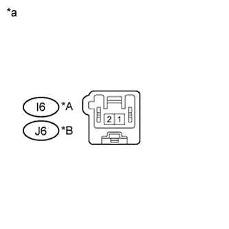
Text in Illustration *A for RH *B for LH *a Component without harness connected
(Front No. 3 Speaker Assembly)
Resistance check
-
Measure the resistance according to the value(s) in the table below.
Standard Resistance for 12 Speakers Tester Connection Condition Specified Condition I6-1 - I6-2 Always 3.2 to 4.8 Ω J6-1 - J6-2 Always 3.2 to 4.8 Ω for 15 Speakers Tester Connection Condition Specified Condition I6-1 - I6-2 Always 4.8 to 6.4 Ω J6-1 - J6-2 Always 4.8 to 6.4 Ω
-
NG
REPLACE FRONT NO. 3 SPEAKER ASSEMBLY Click here
OK
-
-
INSPECT FRONT NO. 4 SPEAKER ASSEMBLY
-
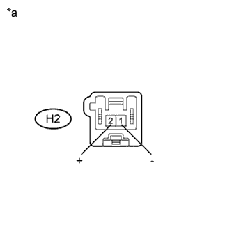
Text in Illustration *a Component without harness connected
(Front No. 4 Speaker Assembly)
Resistance check
-
Measure the resistance according to the value(s) in the table below.
Standard Resistance for 12 Speakers Tester Connection Condition Specified Condition H2-1 (-) - H2-2 (+) Always 4.8 to 7.2 Ω for 15 Speakers Tester Connection Condition Specified Condition H2-1 (-) - H2-2 (+) Always 4.6 to 7.0 Ω
-
NG
REPLACE FRONT NO. 4 SPEAKER ASSEMBLY Click here
OK
-
-
INSPECT REAR NO. 1 SPEAKER ASSEMBLY
-
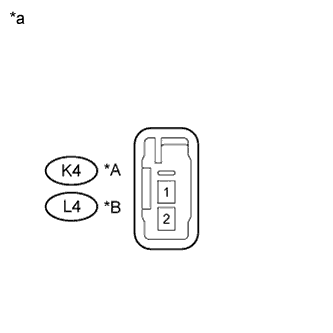
Text in Illustration *A for RH *B for LH *a Component without harness connected
(Rear No. 1 Speaker Assembly)
Resistance check
-
Measure the resistance according to the value(s) in the table below.
Standard Resistance for 12 Speakers Tester Connection Condition Specified Condition K4-1 - K4-2 Always 3.2 to 4.8 Ω L4-1 - L4-2 Always 3.2 to 4.8 Ω for 15 Speakers Tester Connection Condition Specified Condition K4-1 - K4-2 Always 4.8 to 7.2 Ω L4-1 - L4-2 Always 4.8 to 7.2 Ω
-
NG
REPLACE REAR NO. 1 SPEAKER ASSEMBLY Click here
OK
-
-
INSPECT REAR NO. 2 SPEAKER ASSEMBLY
-
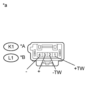
Text in Illustration *A for RH *B for LH *a Component without harness connected
(Rear No. 2 Speaker Assembly)
Resistance check
-
Measure the resistance according to the value(s) in the table below.
Standard Resistance Tester Connection Condition Specified Condition K1-1 (+TW) - K1-2 (-TW) Always 10 kΩ or higher K1-1 (+TW) - K1-3 (+) Always Below 1 Ω K1-2 (-TW) - K1-4 (-) Always Below 1 Ω L1-1 (+TW) - L1-2 (-TW) Always 10 kΩ or higher L1-1 (+TW) - L1-3 (+) Always Below 1 Ω L1-2 (-TW) - L1-4 (-) Always Below 1 Ω
-
NG
REPLACE REAR NO. 2 SPEAKER ASSEMBLY Click here
OK
-
-
REPLACE REAR NO. 2 SPEAKER ASSEMBLY
-
Check that the malfunction disappears when a known good speaker is installed Click here.
OK Malfunction disappears. Tech Tips
-
Connect all the connectors to the rear No. 2 speaker assemblies that were disconnected.
-
When there is a possibility that either the right or left rear speaker is defective, inspect by interchanging the right one with the left one.
-
Perform the above inspection on both LH and RH sides.
-
NG
INSPECT REAR NO. 3 SPEAKER ASSEMBLY Click here
OK
END (REAR NO. 2 SPEAKER ASSEMBLY WAS DEFECTIVE)
-
-
INSPECT REAR NO. 3 SPEAKER ASSEMBLY
-
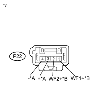
Text in Illustration *A for 12 Speakers *B for 15 Speakers *a Component without harness connected
(Rear No. 3 Speaker Assembly)
Resistance check
-
Measure the resistance according to the value(s) in the table below.
Standard Resistance for 12 Speakers Tester Connection Condition Specified Condition P22-3 (+) - P22-4 (-) Always 1.6 to 2.4 Ω for 15 Speakers Tester Connection Condition Specified Condition P22-2 (WF2+) - P22-1 (WF1+) Always 11.6 to 12.4 Ω
-
-
Proceed to the next step based on the inspection result.
Result Condition Proceed to OK (for 15 Speakers, w/ Telematics Transceiver) A OK (for 12 Speakers, w/ Telematics Transceiver) B OK (w/o Telematics Transceiver) C NG D
B
INSPECT TELEMATICS TRANSCEIVER Click here
C
PROCEED TO NEXT SUSPECTED AREA SHOWN IN PROBLEM SYMPTOMS TABLE Click here
D
REPLACE REAR NO. 3 SPEAKER ASSEMBLY Click here
A
-
-
INSPECT QUARTER SIDE SPEAKER ASSEMBLY
-
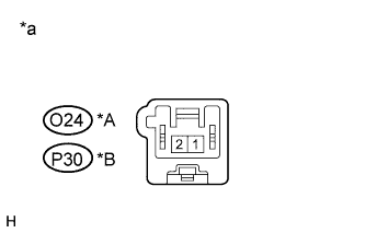
Text in Illustration *A for RH *B for LH *a Component without harness connected
(Quarter Side Speaker Assembly)
Resistance check
-
Measure the resistance according to the value(s) in the table below.
Standard Resistance Tester Connection Condition Specified Condition O24-1 - O24-2 Always 4.6 to 7.0 Ω P30-1 - P30-2 Always 4.6 to 7.0 Ω
-
-
Proceed to the next step based on the inspection result.
Result Condition Proceed to OK (w/ Telematics Transceiver) A OK (w/o Telematics Transceiver) B NG C
B
PROCEED TO NEXT SUSPECTED AREA SHOWN IN PROBLEM SYMPTOMS TABLE Click here
C
REPLACE QUARTER SIDE SPEAKER ASSEMBLY Click here
A
-
-
INSPECT TELEMATICS TRANSCEIVER
-
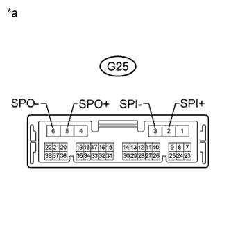
Text in Illustration *a Component without harness connected
(Telematics Transceiver)
Resistance check
-
Measure the resistance according to the value(s) in the table below.
Standard Resistance Tester Connection Condition Specified Condition G25-2 (SPI+) - G25-5 (SPO+) Always Below 1 Ω G25-3 (SPI-) - G25-6 (SPO-) Always Below 1 Ω G25-2 (SPI+) - G25-3 (SPI-) Always 10 kΩ or higher G25-5 (SPO+) - G25-6 (SPO-) Always 10 kΩ or higher G25-3 (SPI-) - Body ground Always 10 kΩ or higher G25-2 (SPI+) - Body ground Always 10 kΩ or higher
-
NG
REPLACE TELEMATICS TRANSCEIVER Click here
OK
PROCEED TO NEXT SUSPECTED AREA SHOWN IN PROBLEM SYMPTOMS TABLE Click here
-